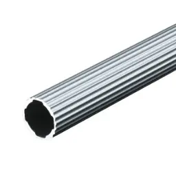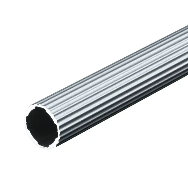


GF-N sliding profile
Smooth-surface Green Frame Ø 28 series profile on which parts and boxes slide without snagging: guides, chutes and sliding surfaces. 0.46 kg/m, 4000 mm bar or cut to length.
Green Frame · GF-N Ø 28 profiles
GF-N sliding profile: smooth aluminium guide for sliding parts and boxes
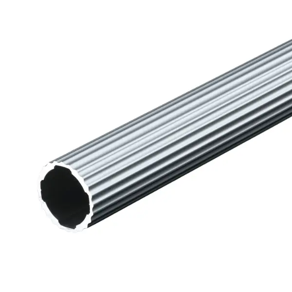
The smooth-surface Green Frame profile: parts, containers and boxes slide over it without snagging. You use it as a guide and sliding surface in chutes, workstations and gravity mechanisms, connected with 28 series inner connectors. It weighs 0.46 kg/m.
Why choose it
Smooth sliding
The smooth surface lets parts and containers slide without snagging.
Rounded lead-in
With the SR25 end cap at the end, the part enters the guide without catching.
Flush joints
It connects with GF-N inner connectors: no protrusions along the parts' path.
Lightweight
0.46 kg/m, slightly more than the standard pipe, with a higher moment of inertia.
Choose it if…
- Parts or boxes have to slide on the profile.
- You are building gravity guides and chutes for loose parts.
- You want flush joints, with no protrusions along the path.
Choose another solution if…
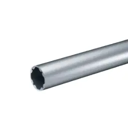
- The pipe has to turn like a roller: GF-N round roller profile →
- The part has to run on rollers along a slot: GF-N profile with C10 slot →
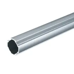
- You need a structural pipe for uprights and cross members: GF-N profile →
Not sure which one to choose? Use the Green Frame quick guide →
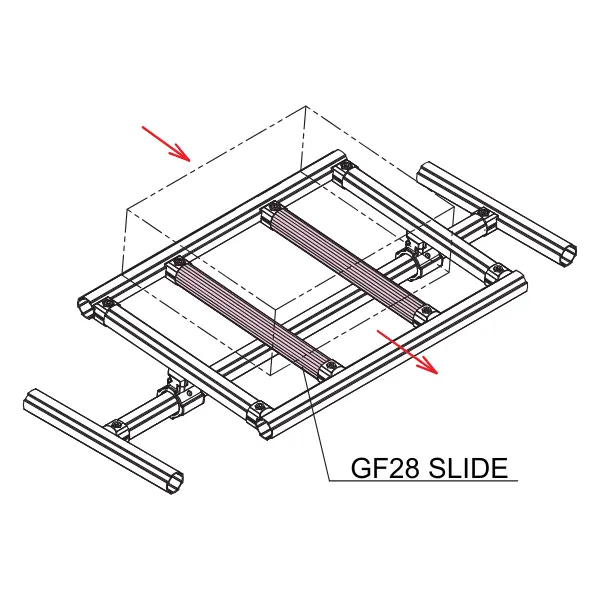
Application example
The sliding profile is used where material moves over the structure:
- Gravity chutes for parts and small containers
- Entry guides at assembly workstations
- Sliding surfaces for boxes between two workstations
What you complete it with
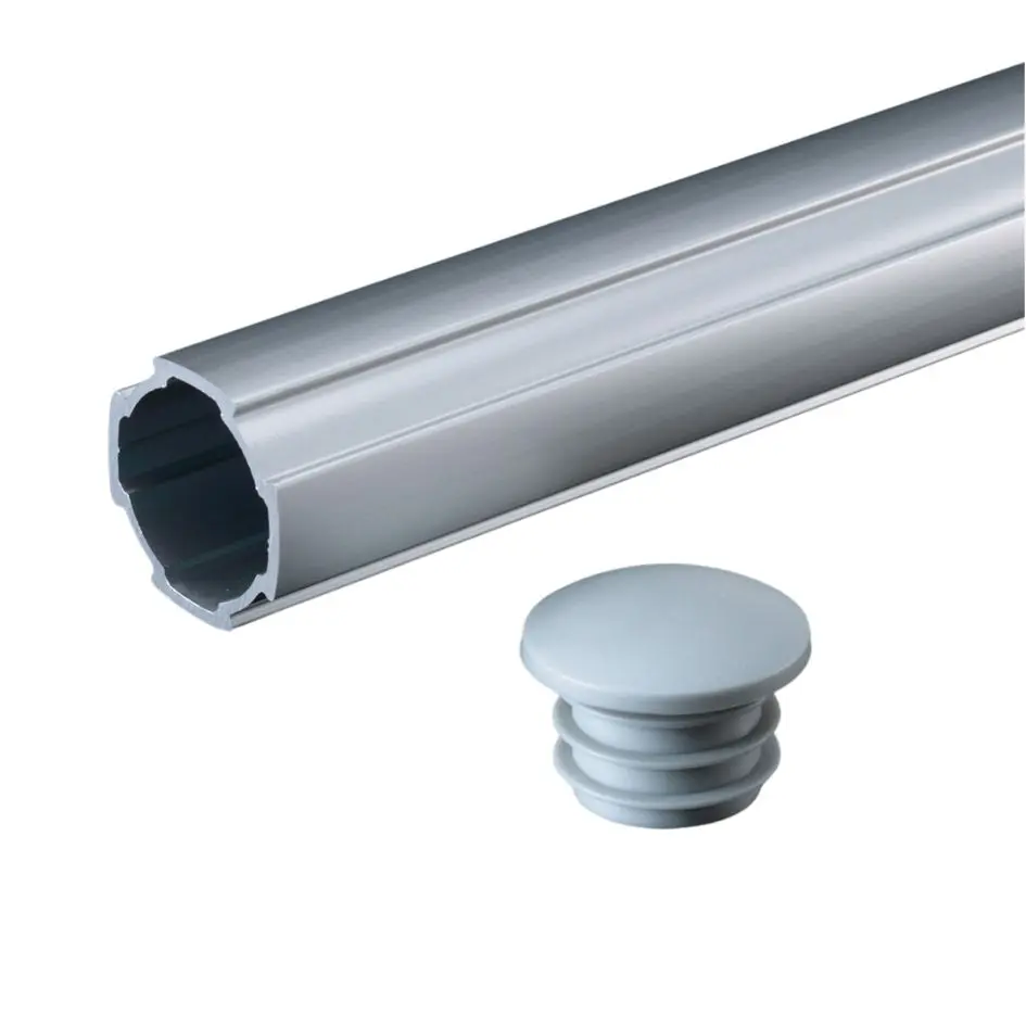
Rounded inner end cap SR25
Rounded lead-in: the part enters the guide without catching.
View product →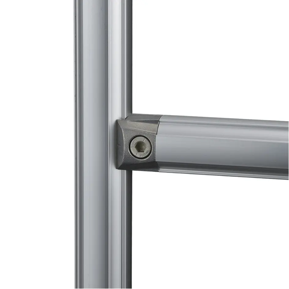
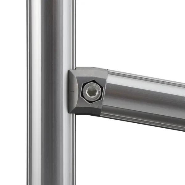
The right slope depends on the weight and material of the parts: we choose it with you.
How to use it
Three tips for smooth sliding:
Fit the lead-in
At the guide entry use the SR25 rounded end cap: parts do not catch on the end of the pipe.
Set the slope
Tilt the guide with fixed-angle joints, such as the 10° inner connector, or with rotating and hinged connectors.
Flush joints
Connect the profile with GF-N inner connectors, so nothing protrudes along the path.
For heavy boxes or long runs at a low slope, a roller track is better: we will recommend the solution.
The LeanProducts service
From drawing to finished structure, with a single point of contact:
Design and load calculation
We start from your sketch or dimensions: we choose profiles and connectors and check spans, joints and loads.
Cut to length
We cut the profiles in our workshop to the lengths in the design, ready to assemble.
Kit or assembled structure
You receive the kit with the cut parts and the list of components, or the structure already assembled.
Spare parts and modifications
When the process changes we supply components and new cuts to modify or extend the structure.
Send us a sketch, a photo or the overall dimensions: we will reply with codes, quantities and cut lengths.
Technical data
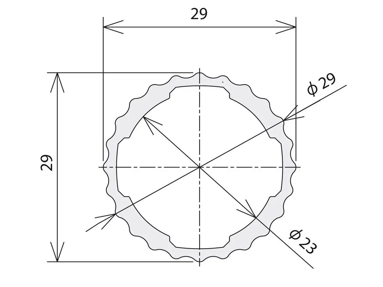
| Specification | Value |
|---|---|
| Code | GFF-006 |
| Series | GF-N, Ø 28 mm |
| Surface | Smooth, for sliding parts and containers |
| Length | 4000 mm bar or cut to length |
| Weight | 0.46 kg/m |
| Material and finish | Anodised extruded aluminium |
| Moment of inertia | Ix = Iy = 1.47 × 10⁴ mm⁴ |
| Section modulus | Zx = Zy = 1.01 × 10³ mm³ |
| Suitable connectors | GF-N inner connectors |
| End caps | SR25 rounded inner end cap GFA-404 |
The permissible load depends on span, profile orientation and joints: send us dimensions and weights and we will check the structure.
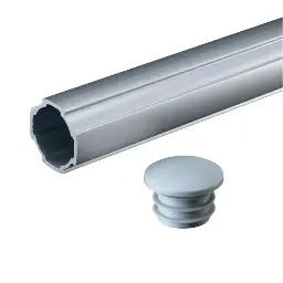 GF-N SR25 rounded inner end capSR25 rounded end cap
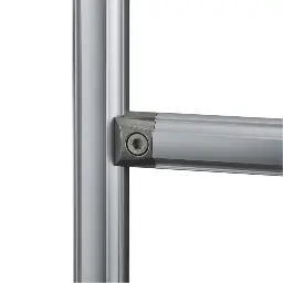 Inner 90° connector GF-NInner 90° connector
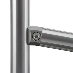 Inner 10° connector GF-N10° inner connector for inclined guides
 GF-N round roller profileRound roller profile
 GF-N profileStandard GF-N profile
Not sure which profile to use?
Send us a sketch of the structure and the weight it has to support: we will tell you the profiles, connectors and cut lengths.