Quick guide · Green Frame by SUS
Green Frame: how to choose pipes, connectors and accessories
The aluminium pipe system for workstations, shelving and gravity flow racks, trolleys, guards and karakuri mechanisms. Answer 3 questions and we will point you to the right profile, connectors and accessories, and explain why.
- No welding, no paintingAnodised aluminium pipes and connectors tightened with an Allen key: the structure is built on the shop floor, not in a workshop.
- Easy to modify over timeWhen the process changes, loosen the connectors, move or shorten the pipes and tighten again: kaizen without throwing anything away.
- Made to measureProfiles as 4000 mm bars or cut to length in our workshop; ready-to-assemble kits or fully assembled structures.
What do you need to build?
Load and footprint?
Determines the pipe series.
You also need…
Choose the most important requirement.
Go to:The three seriesGF-N profilesConnectorsHow to assemble itFeet, castors and roller tracksThe serviceFAQ
The three series: GF-S, GF-N and GF-G
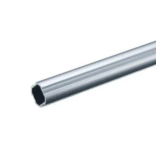
GF-S · Ø 19 mm
0.20 kg/mLight and compact. Light frames, dividers, guards, superstructures and small mechanisms. Combines with GF-N.
Profiles →Connectors →Whole series →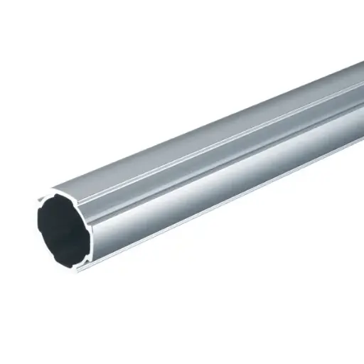
GF-N · Ø 28 mm
0.37 kg/m · 195 N over 1000 mmThe standard. Workstations, shelving and gravity flow racks, trolleys, line-side supermarkets, karakuri: the widest range of profiles, connectors and accessories.
Profiles →Connectors →Whole series →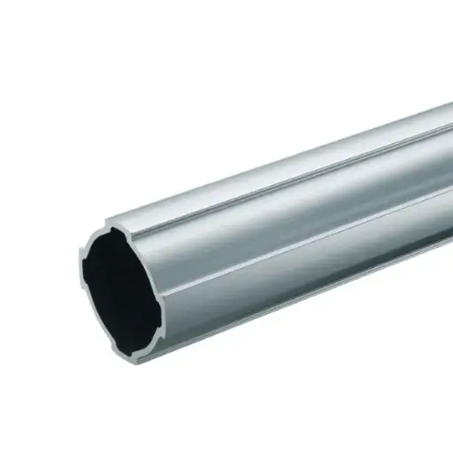
GF-G · Ø 43 mm
0.74 kg/m · 851 N over 1000 mmRigid, for high loads. Uprights and cross-members for heavy benches, heavily loaded shelving and long spans. Combines with GF-N.
Profiles →Connectors →Whole series →Series comparison
| Series | Pipe | Weight | Moment of inertia | Load at centre, 1000 mm span | Profiles | Connectors |
|---|---|---|---|---|---|---|
| GF-S | Ø 19 mm light and compact | 0.20 kg/m | 0.27 × 10⁴ mm⁴ | Light loads frames, dividers, guards | Standard, with C6 slot, F22, F35, W, Hard | Outer and inner 90°, corner, 45°, cross, parallel, brace, rotating mixed with Ø 28 and Ø 43 |
| GF-N | Ø 28 mm the standard | 0.37 kg/m | 1.16 × 10⁴ mm⁴ | 195 N 5 mm deflection; 779 N over 500 mm | Standard, W, C10 slot, F35, F50, T, Hard, LS, sliding, round for rollers, linear guide | The widest range: inner, outer, corner, 45°, hinged, cross, rotating, sliding aluminium screw at 11 N·m |
| GF-G | Ø 43 mm rigid structures | 0.74 kg/m | 5.07 × 10⁴ mm⁴ | 851 N 5 mm deflection | Standard, with C10 slot, W, Hard, P150 twin pipe | Outer and inner 90°, reinforced H and M, corner, 45°, hinged, linear mixed G-N; M8 bolt at 24.9 N·m |
Point load at the centre of a pipe fixed at both ends with connectors, span measured between uprights, 5 mm deflection per metre. In a structure, joints and supports also matter: we carry out the full check on the project.
GF-N Ø 28 profiles compared
| Profile | Use | Weight | Load at centre, 1000 mm span | Connectors | End caps and accessories |
|---|---|---|---|---|---|
| GF-N profile | Uprights, cross-members and frames: the basis of the system | 0.37 kg/m | 195 N | All GF-N, inner and outer | Standard inner end cap GFA-400; alternatively aluminium, expanding, rounded, ESD; outer end cap |
| GF-N W profile | Long cross-members and loaded tops twin pipe 65 × 28 mm, about 10 times stiffer when upright | 0.79 kg/m | About 1950 N upright 388 N flat | Outer 90° for W profile 1000 N slip resistance; GF-N inner | Series 28 inner end caps |
| GF-N profile with C10 slot | Trolley bases, plate castors, panels, hooks, rollers 10 mm slot for T-nuts | 0.68 kg/m | 200 N with slot underneath 334 N with slot at the side | GF-N outer inner for C10 slot profile | C10 slot insert, C10 slot hook, slot roller kits |
| GF-N F35 profile | Cross-member, label holder and tray support 35 mm flat fin | 0.67 kg/m | 507 N fin horizontal 566 N fin vertical | GF-N inner and outer | Series 28 inner end caps |
| GF-N F50 profile | Cross-member and label holder in one piece 50 mm flat fin for small parts bins and signs | 0.65 kg/m | — | GF-N connectors | Series 28 inner end caps |
| Reinforced GF-N T profile | Loaded cross-members about 1.5 times the bending strength of GF-N | 0.79 kg/m | 289 N | GF-N outer | Inner end cap for T profile, outer end cap |
| GF-N Hard profile | Joints exposed to impacts and loads thick wall, about 1.7 times GF-N; GF-S slides inside | 0.76 kg/m | 338 N | GF-N outer dedicated inner 90° | Dedicated M12 threaded insert: 3000 N with levelling foot |
| GF-N LS profile | Sliding tables and karakuri linear slide rail, free clamping area for connectors | 0.61 kg/m | — | GF-N on the pipe clamping area | Series 28 inner end caps |
| GF-N LS profile with S slot | Linear slide plus S slot for parts and panels | 0.69 kg/m | — | GF-N on the pipe clamping area | In-line anti-return, 300 N |
| GF-N sliding profile | Guides, chutes and sliding surfaces smooth surface: parts and boxes slide without snagging | 0.46 kg/m | — | GF-N inner | Rounded inner end cap |
| GF-N round roller profile | Rollers, chutes and karakuri with a swivel pin connector at each end it becomes a roller | 0.51 kg/m | — | Rotating pivot connector | Rounded inner end cap |
| GF-N linear guide profile | Rail for linear rollers slides, drawers and pull-out tops | 1.45 kg/m | — | Linear roller, 10 N per roller | Bar cut to the stroke length |
All profiles in anodised extruded aluminium, as 4000 mm bars or cut to length. “—” = load not stated: we calculate it on the project. GF-S and GF-G profiles in their respective categories: GF-S profiles · GF-G profiles.
Which connector for each joint
| Joint | When to use it | Holding force (GF-N) | GF-N Ø 28 | GF-S Ø 19 | GF-G Ø 43 |
|---|---|---|---|---|---|
| Outer 90° | Wraps around the end of the cross-member and clamps it to the upright: the most widely used joint. | 800 N against slipping 1500 N pull-out with screw in the notch | Outer 90°Reinforced outer 90° | Outer 90° | Outer 90°Reinforced outer 90° HDouble-reinforced outer 90° M |
| Inner 90° | Slides into the pipe and stays flush: a clean structure with no protrusions. | 800 N against slipping 9 N·m bending | Inner 90°Inner for C10 slot profile | Inner 90° | Inner 90° |
| 90° corner | Closes the corner where two pipes end: frames, handles, closed frames. | 20 N·m outer corner | Outer corner connectorInner corner connector | Outer corner connector | Outer corner connector |
| A 45° | Diagonal braces at exactly 45°, no adjustment needed. | 700 N outer; 600 N inner | Outer 45°Inner 45° | Inner 45° | Outer 45° |
| Hinged 0–180° | Free angle, locked by tightening the bolt: braces and inclined tops. | 800 N inner; 700 N outer | Inner hingedOuter hinged | — | Inner hinged |
| Cross | Locks two overlapping pipes without cutting them: roller track supports, grids, movable levels. | 800 N against slipping | CrossRotating cross | CrossRotating cross | Cross, also clamps Ø 43 |
| Parallel | Places two pipes side by side: double cross-members, mount guides and supports. | — | ParallelReinforced parallelParallel P15 | Parallel | Parallel, also clamps Ø 43 |
| Linear | Joins two pipes end to end, for runs longer than the bar. | — | Linear | — | Linear |
| 45° brace | Strut under the 90° joint: for brackets and cantilever arms. | 40 N·m 95 N·m in the long version | 45° braceLong 45° brace | 45° brace | 45° brace, with the GF-G inner 90° |
| Mixed S-N and G-N | Join different series: use the right diameter at every point. | 1100 N outer 90° G-N | Outer 90° G-NInner 90° G-N | Outer 90° S with N/GCross S with N/GParallel S with N/G45° brace S with N/G | Outer 90° G-NInner 90° G-N |
Holding force: values of the typical GF-N connector for the joint. In the GF-G series the outer 90° holds 2500 N against slip, the inner 1700 N. All connectors: GF-N · GF-S · GF-G.
How to assemble it
One Allen key
- Loosen the screw, insert the pipe, bring it into position and tighten: no welding, drilling or painting.
- GF-N series: 5 mm hex key, 11 N·m with the aluminium screw.
- GF-G series: M8 bolt at 24.9 N·m. Recheck the tightening within one month of assembly, then once a year.
Cut to length
- Profiles as 4000 mm bars or cut to length in our workshop, ready to assemble.
- Cross-member between two GF-N uprights with 90° connectors, inner or outer: length = overall dimension − 88 mm, 44 mm per side.
- For the GF-G series, corners and braces, we calculate the cutting lengths on the project.
Joints and braces
- A cantilever without a brace carries little: the standard connector allows 9–11 N·m at the root of the arm.
- With the 45° brace the joint reaches 40 N·m, with the long brace 95 N·m.
- GF-N W must be mounted upright: that way it is about 10 times stiffer than the single pipe.
ESD structures: fit the ESD continuity clip between pipe and connector and use ESD versions of the inner end caps and threaded inserts.
Feet, castors and roller tracks
Feet and castors
| Product | Mounting | Capacity |
|---|---|---|
| Feet and threaded inserts | ||
| Plastic levelling foot | M8 or M12 threaded insert in the GF-N pipe Ø 30 or 50 mm base | Set by the threaded insert 1200 N M8 · 1250 N M12 |
| Steel levelling foot | M12 stem, 80 mm M12 threaded insert, or dedicated insert on GF-N Hard | 1250 N 3000 N on GF-N Hard |
| Levelling foot with anchor hole | M12 stem, Ø 60 base with hole levelled structure anchored to the floor | 1250 N with the M12 threaded insert |
| Inner rubber foot GF-N | Fits into the bottom of the GF-N pipe, no threaded insert needed | 200 N |
| M12 threaded insert for foot/castor GF-N | In the bottom of the Ø 28 pipe for feet and castors with M12 stem | 1250 N ESD 500 N |
| M16 threaded insert for foot/castor GF-G | In the bottom of the Ø 43 pipe for feet and castors with M16 stem | 5800 N ESD 1000 N |
| M6 threaded insert for foot GF-S | In the bottom of the Ø 19 pipe, for feet with M6 stem | — |
| Castors | ||
| Plate-mounted castor | Under the C10 slot profile 4 M8 screws and hammer-head nuts | 150 kg per castor Ø 100 or 125 mm |
| Castor with centre hole | M12 screw in the M12 threaded insert swivel, with or without brake | 150 kg per castor the threaded insert holds 1250 N |
| Heavy-duty plate-mounted castor | Plate-mounted, under the base fixed or swivel with brake, Ø 160 mm | 400 kg per castor |
| Light-duty braked castor | M8 stem in the M8 threaded insert swivel with brake | 30 kg per castor |
| Castor bracket next to the foot GF-N | M12 castor next to the M12 levelling foot on the same GF-N upright | 1900 N type A 900 N type B |
| Foot-operated parking brake GF-N | On C10 slot profile the foot lowers when you press the pedal | Locking force 392 N |
For a trolley's load capacity count 3 castors out of 4 (2 on uneven floors or with steps). The limit of a levelling foot is set by the threaded insert it screws into. All models: feet and castors.
Gravity roller tracks
For FIFO shelving, flow racks and line-side supermarkets on a Ø 28 pipe frame: we cut the roller tracks to the lane depth. We define the slope and the number of supports on the project.
Roller tracks
- Roller track · standard, also ESD
- Roller track with edge · with side edge
- Twin-wheel roller track · double wheel
- HD roller track · HD, for heavy containers
- Rounded roller track · rounded
Guides, hooks and clips
- Aluminium side guide · keeps containers in the lane
- Aluminium centre guide · separates or centres containers
- Roller track hook · basic connection between roller track and frame
- End hook for roller tracks · at the infeed or outfeed end
- Bridge hook for roller tracks · bridge mounting
- Roller track fixing clip
- Roller track retaining clip
Flow control
- High stop hook for roller tracks · at the outfeed end, picking side
- Low stop hook for roller tracks · low stop
- Roller track brake · slows down on the descent
- Friction roller · friction braking
- Anti-return stop for roller track · one-way flow
- GF-N anti-return mechanism · 200 N, also for chutes
- Heavy-duty singulator GF-N · one at a time, up to 100 kg in the queue
Full range: gravity roller tracks.
The LeanProducts service
- Design and load calculationWe start from your sketch or dimensions: we choose profiles and connectors and check spans, joints and loads.
- Cut to lengthWe cut the profiles in our workshop to the lengths in the design, ready to assemble.
- Kit or assembled structureYou receive the kit with the cut parts and the list of components, or the structure already assembled.
- Spare parts and modificationsWhen the process changes we supply components and new cuts to modify or extend the structure.
Send us a sketch, a photo or the overall dimensions: we will reply with codes, quantities and cut lengths.
Frequently asked questions
GF-N, GF-S or GF-G: which series should I choose?
Start with GF-N, the Ø 28 pipe: it has the widest range of profiles, connectors and accessories and suits workstations, shelving, flow racks, trolleys and karakuri. GF-S Ø 19 is lighter (0.20 kg/m versus 0.37) and is used for small frames, dividers, guards and superstructures. GF-G Ø 43 carries more than four times as much as GF-N: over 1000 mm, 851 N at mid-span versus 195 N, for heavily loaded uprights and cross members. With mixed connectors you use the right diameter at every point of the same structure.
Inner or outer connector: what’s the difference?
The inner connector slides into the pipe and sits flush: the structure is clean, with nothing sticking out; it fits standard GF-N, W, F35 and sliding profiles. The outer connector wraps around the pipe end and also fits T, Hard and C10-slot profiles. In the GF-N series both hold 800 N against slipping and 420 N against pull-out; the outer connector with a screw in the notch reaches 1500 N pull-out, useful where the cross member hangs from its joints.
How much load can a Green Frame pipe carry?
It depends on the span between uprights. GF-N carries 195 N at mid-span over 1000 mm and 779 N over 500 mm, with 5 mm deflection per metre. GF-N W mounted upright reaches about 1950 N over 1000 mm, GF-G 851 N. In a structure the joints count too: an outer 90° GF-N connector holds 800 N against slipping, and cantilevers without a brace carry little. We do the full calculation on your project.
How do you work out the cut length of the pipes?
For a cross member between two GF-N uprights with 90° connectors, inner or outer, subtract 88 mm from the overall dimension: 44 mm per side. For the GF-G series, corner pieces and braces the allowances differ: we work them out for you. Send us the dimensions or a sketch and we will prepare the cutting list; we cut the profiles in our own workshop.
How do I make a structure mobile?
On a trolley the base is built with the GF-N profile with C10 slot: you fix 150 kg plate castors in the slot with M8 screws and hammer nuts, and the foot-operated lock holds it in place. On workbenches and shelving you can screw bolt-hole castors into the M12 threaded insert or fit the castor next to the levelling foot, so the structure moves on castors and stands on its feet. For load capacity, count 3 castors out of 4.
How do you build a flow rack with gravity roller tracks?
A Ø 28 pipe frame, inclined rails with the rotating inner 90° connector, which locks the cross member at the chosen angle, and roller tracks cut to the depth of the lane. You hook them onto the pipes with hooks and clips, fit the end stop on the picking side and, where needed, a brake, friction roller or anti-return; the side guides keep the containers in the lane. For EPA areas there are ESD roller tracks.
What is karakuri and what do you need to build it?
It is a mechanism that moves without motors, using gravity, springs, cable, pulleys and counterweights: flaps that tip over, stops that release one container at a time, decks that lift. On GF-N pipe you use rotating and sliding connectors, tension springs, Ø 2 mm cable, pulleys, cable clamps, singulators and rollers. We design and test the mechanism with you.
Can you help me design the structure?
Yes. We start from a sketch, a photo or the overall dimensions and the load the structure has to carry: we choose the series, profiles and connectors and check spans, joints and loads. We cut the profiles in our own workshop and deliver the kit with the parts list or the assembled structure; when your process changes we supply spare parts and new cuts.