- All Products
- Green Frame
- GF-N Ø 28 mm
- Profiles
- GF-N linear guide profile
GF-N linear guide profile
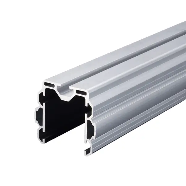
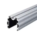
https://leanproducts.eu/shop/gff-m05-gf-n-linear-guide-profile-360 https://leanproducts.eu/web/image/product.template/360/image_1920?unique=e198dfeAluminium rail from the Green Frame GF-N series for linear rollers: guides carriages, slides and moving parts in a straight line. 1.45 kg/m, 4000 mm bar or cut to the stroke length.
Green Frame · GF-N Ø 28 profiles
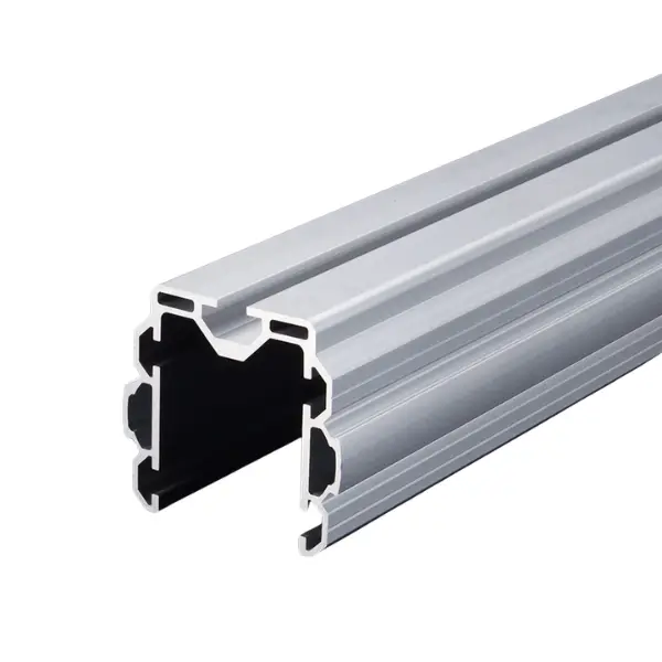
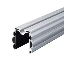
GF-N linear guide profile: aluminium rail for linear rollers
An extruded aluminium rail from the GF-N series in which linear rollers run: you use it for carriages, slides and moving parts that have to run straight along the structure. It is a guide profile, not an upright: it works together with the Green Frame pipes that form the frame.
Why choose it
Straight stroke
The linear rollers run in the rail: the moving part stays aligned over the whole stroke.
Stiff
Moment of inertia up to 23.04 × 10⁴ mm⁴: the guide does not bend under the moving part.
For karakuri
Slides, transfer carriages and parts that traverse by gravity or counterweight.
Custom stroke
We cut it to the stroke length you need.
Choose it if…
- A moving part has to run straight on linear rollers.
- You need a stiff guide for slides or small carriages.
- You are building transfer or karakuri mechanisms.
Choose another solution if…
- You want a slide on a pipe that remains part of the structure: GF-N LS profile →
- You need a pipe for uprights and cross members: GF-N profile →
- The rollers can run in a 10 mm slot: GF-N profile with C10 slot →
Not sure which one to choose? Use the Green Frame quick guide →
How to use it
Rail, rollers and structure:
Linear rollers
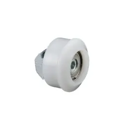
GFW-645 linear rollers run in the rail: each carries 10 N and is tightened to 2 N·m.
Count the rollers
The number of rollers depends on the weight of the moving part: at 10 N per roller we calculate it with you.
It is not an upright
It is a guide profile: for uprights and cross members use Green Frame pipes.
Tell us the stroke and the weight of the moving part: we will propose rail, rollers and fixings.
The LeanProducts service
From drawing to finished structure, with a single point of contact:
Design and load calculation
We start from your sketch or dimensions: we choose profiles and connectors and check spans, joints and loads.
Cut to length
We cut the profiles in our workshop to the lengths in the design, ready to assemble.
Kit or assembled structure
You receive the kit with the cut parts and the list of components, or the structure already assembled.
Spare parts and modifications
When the process changes we supply components and new cuts to modify or extend the structure.
Send us a sketch, a photo or the overall dimensions: we will reply with codes, quantities and cut lengths.
Technical data
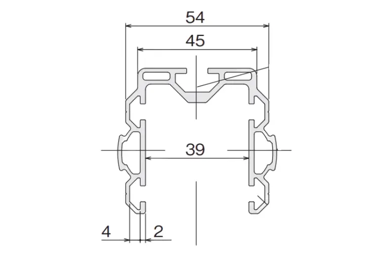
| Specification | Value |
|---|---|
| Code | GFF-M05 |
| Series | GF-N, guide profile |
| Type | Rail for linear rollers |
| Length | 4000 mm bar or cut to length |
| Weight | 1.45 kg/m |
| Material and finish | Anodised extruded aluminium |
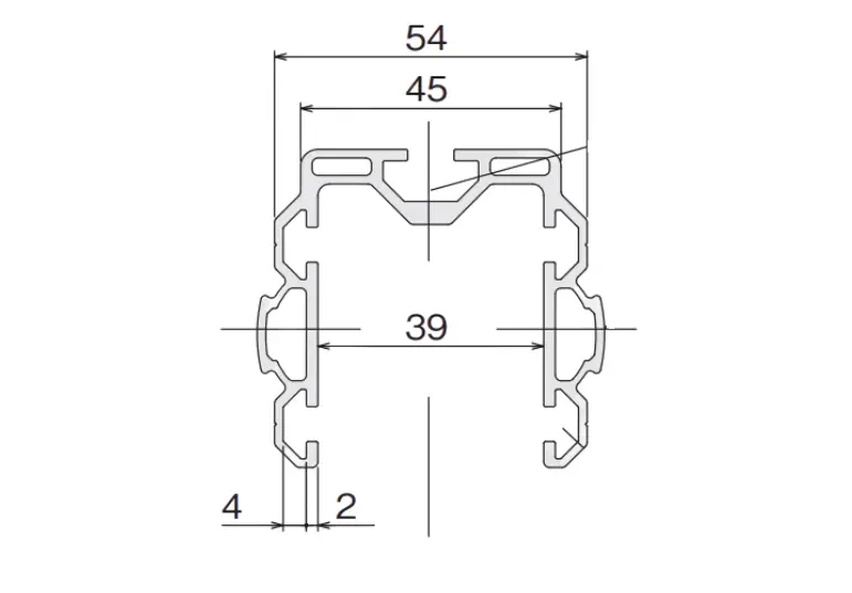
| Moment of inertia | Ix = 14.98 × 10⁴ mm⁴ · Iy = 23.04 × 10⁴ mm⁴ |
| Section modulus | Zx = 4.36 × 10³ mm³ · Zy = 7.68 × 10³ mm³ |
| Rollers | GFW-645 linear roller: 10 N per roller, tightening torque 2 N·m |
The load capacity of the guide depends on the number of rollers and how it is fixed to the frame: we check it with you on the project.
Not sure which profile to use?
Send us a sketch of the structure and the weight it has to support: we will tell you the profiles, connectors and cut lengths.
Specifications
| Length | 4000 |
| Material | Anodised extruded aluminium |
| Weight | 1.45 kg/m |
| Tags | |
|---|---|
| Tags |
SUS
|
It is the rail in which linear rollers run: it guides carriages, slides and moving parts that have to move in a straight line along the structure.
GFW-645 linear rollers: each carries 10 N and is tightened to 2 N·m. We calculate the number of rollers based on the weight of the moving part.
No, it is a guide profile. For the structure use Green Frame pipes (GF-N, GF-G or GF-S) and fit the guide where movement is needed.
The LS is a Ø 28 structural pipe with a rail for the linear slide, and its grip surface stays free for connectors. The linear guide profile is a dedicated rail for linear rollers, heavier (1.45 kg/m) and stiffer.
The bar is 4000 mm and we cut it to the stroke length you need.
Moment of inertia Ix = 14.98 × 10⁴ mm⁴ and Iy = 23.04 × 10⁴ mm⁴: far more than the standard GF-N pipe (1.16 × 10⁴). It weighs 1.45 kg/m.
The standard GF-N profile is suitable for most uprights and cross members. If a cross member is long or loaded use the GF-N W fitted upright (about 10 times stiffer), or the T (about 1.5 times) or the Hard (about 1.7 times, also for joints that take impacts), which have the same diameter. To fix plate castors, panels or rollers with T-nuts choose the profile with C10 slot; F35 and F50 have a flat flange for labels, small parts holders and supports. The sliding profile has a smooth surface for sliding parts and boxes, the round roller profile becomes a roller with the pin connectors, LS and LS with S slot carry a linear slide and the linear guide profile is the track for the linear rollers.
The GF-N Ø 28 is the standard for workstations, flow racks and trolleys. The GF-S Ø 19 weighs about half as much (0.20 kg/m versus 0.37) and is for light frames, dividers, guards and small mechanisms. The GF-G Ø 43 is for uprights and cross members that have to carry a lot: over a 1000 mm span it supports 851 N at the centre versus 195 N for the GF-N, for the same deflection. It is often worth mixing them, for example GF-G uprights and GF-N cross members joined by mixed connectors.
Yes. Green Frame profiles can be ordered as 4000 mm bars or cut to the length you need: we do the cutting ourselves, in our workshop. Give us the dimensions of the pieces or send us a sketch of the structure and we will prepare the cutting list.
Yes. The standard series is GF-N (Ø 28 mm pipe); GF-S (Ø 19 mm) is lighter and more compact, GF-G (Ø 43 mm) is for stiffer structures. There are mixed connectors that join pipes from different series, for example a Ø 19 or Ø 43 pipe to a Ø 28 pipe, so you use the right diameter at every point of the structure.
No. The connectors are fixed to the pipe with hex socket screws: a hex key is all you need. Loosen the screw, insert the pipe, bring it into position and tighten. No welding, drilling or painting.
Yes, it is the strength of the pipe system: loosen the connectors, move or replace the pipes and retighten. You can raise a shelf, extend a workbench or reuse the components in another structure when the process changes, with continuous improvement in mind.
Yes. We can design the structure (workstation, flow rack, trolley, line-side supermarket) with the load calculation and deliver it to you assembled or as a kit with the parts already cut and the list of components.
No. Profiles and connectors are in anodised aluminium: the surface resists corrosion and wear without painting and is easy to clean.
Yes. The range includes conductive components such as ESD inner end caps, ESD clips for electrical continuity between pipe and connector, and ESD inserts for levelling feet and castors. Tell us which EPA area you work in and we will tell you the components to use.