
GF-G W profile
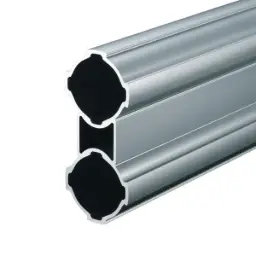
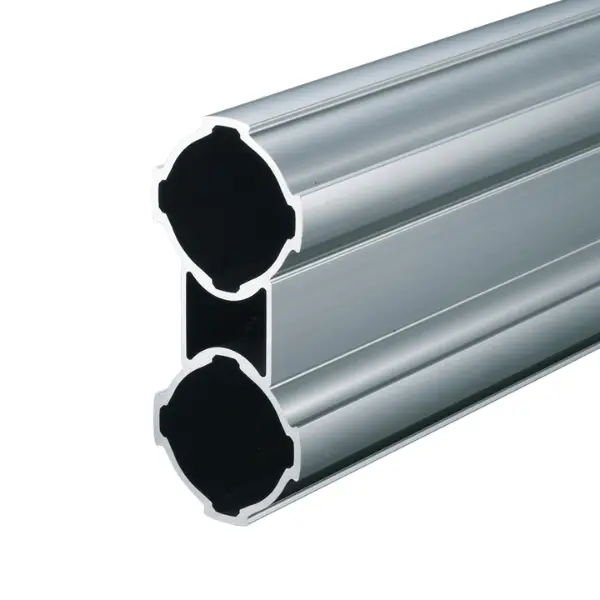
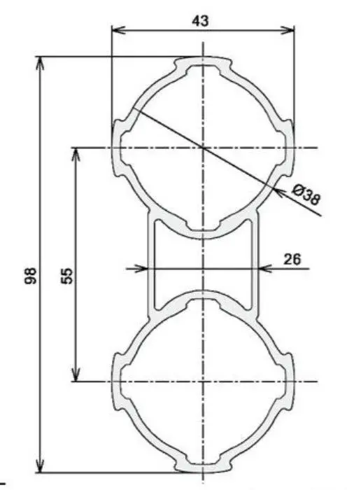
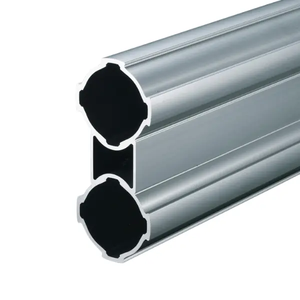
Green Frame twin Ø 43 mm pipe profile, 98 mm high: upright more than 10 times stiffer than GF-G. For heavily loaded cross members and heavy worktops. 1.74 kg/m, 4000 mm bar or cut to length.
Green Frame · GF-G Ø 43 profiles
GF-G W profile: twin Ø 43 mm pipe for heavily loaded cross members
Two Ø 43 mm pipes joined into a 98 mm high profile: upright it has a moment of inertia of 52.42 × 10⁴ mm⁴, more than ten times the GF-G pipe. It is the cross member for high loads on G series structures: heavy worktops, industrial trolley bases, long spans. Even flat, over 1000 mm it takes 1927 N at mid-span with 5 mm of deflection.
Why choose it
Beam-like stiffness
Upright more than ten times the GF-G pipe: the cross member is no longer the weak point.
Strong even flat
Flat, over 1000 mm it takes 1927 N at mid-span with 5 mm of deflection.
In the G series
The Ø 43 pipes are closed with GF-G end caps and work with the series' components.
For industrial loads
Heavy worktops, trolley bases and structures with long spans.
Choose it if…
- The cross members have to carry high loads.
- You want long spans without intermediate supports on a Ø 43 structure.
- The GF-N W is not enough.
Choose another solution if…
- You need to cover very large spans, such as enclosures and gantries: GF-G P150 high-rigidity profile →
- A single Ø 43 pipe is enough: GF-G profile →
- The loads are workstation loads: twin Ø 28 pipe: GF-N W profile →
Not sure which one to choose? Use the Green Frame quick guide →
Application example
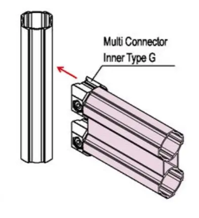
The GF-G W is used as a cross member where loads are high:
- Heavy worktops on G series workbenches
- Trolley bases for industrial loads
- Supermarkets and shelving with long spans
Upright or flat
How the twin Ø 43 pipe works:
Upright
Moment of inertia 52.42 × 10⁴ mm⁴: the cross member outperforms the joints, which become the reference for the load capacity.
Flat
Over 1000 mm it takes 1927 N at mid-span with 5 mm of deflection.
Joints
GF-G connectors hold up to 2500 N against slipping: with the W we always check them on the project.
Send us spans and loads: we calculate joints, uprights and feet.
The LeanProducts service
From drawing to finished structure, with a single point of contact:
Design and load calculation
We start from your sketch or dimensions: we choose profiles and connectors and check spans, joints and loads.
Cut to length
We cut the profiles in our workshop to the lengths in the design, ready to assemble.
Kit or assembled structure
You receive the kit with the cut parts and the list of components, or the structure already assembled.
Spare parts and modifications
When the process changes we supply components and new cuts to modify or extend the structure.
Send us a sketch, a photo or the overall dimensions: we will reply with codes, quantities and cut lengths.
Technical data
| Specification | Value |
|---|---|
| Code | GFF-207 |
| Series | GF-G, Ø 43 mm |
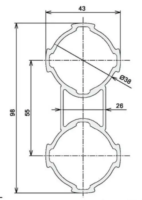
| Cross-section | Two Ø 43 mm pipes joined, 98 × 43 mm, 55 mm centres |
| Length | 4000 mm bar or cut to length |
| Weight | 1.74 kg/m |
| Material and finish | Anodised extruded aluminium |
| Moment of inertia | Ix = 52.42 × 10⁴ mm⁴ (upright) · Iy = 11.47 × 10⁴ mm⁴ |
| Section modulus | Zx = 10.07 × 10³ mm³ · Zy = 5.33 × 10³ mm³ |
| Load at mid-span, 1000 mm span, flat | 1927 N (about 196 kg) with deflection 5/1000 |
| Load at mid-span, 1000 mm span, upright | Beyond the joint capacity: connectors and supports govern |
| Suitable connectors | GF-G Ø 43 connectors (models to be confirmed on the project) |
| End caps | GF-G inner end cap GFA-402 on each pipe |
Loads concentrated at the centre of a pipe fixed at both ends with connectors, span measured between the uprights: in a structure, joints and supports also count, and we carry out the full check on the design.
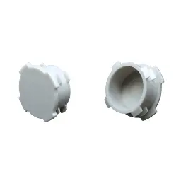 Inner end cap GF-GInner end cap GF-G
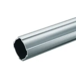 GF-G profileGF-G profile
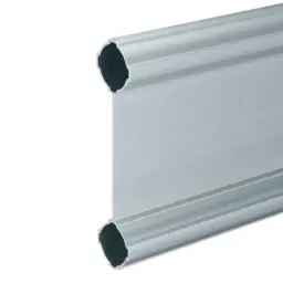 GF-G P150 high-rigidity profileGF-G P150 profile
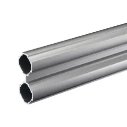 GF-N W profileGF-N W profile
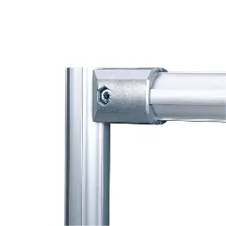 Outer 90° connector GF-GOuter 90° connector GF-G
Not sure which profile to use?
Send us a sketch of the structure and the weight it has to support: we will tell you the profiles, connectors and cut lengths.