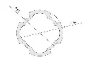
GF-S profile
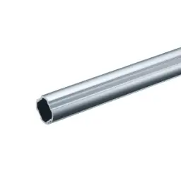
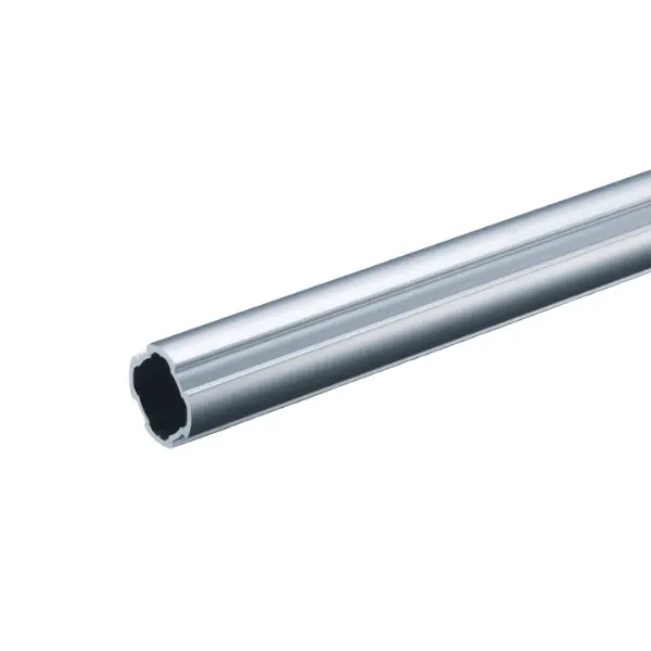
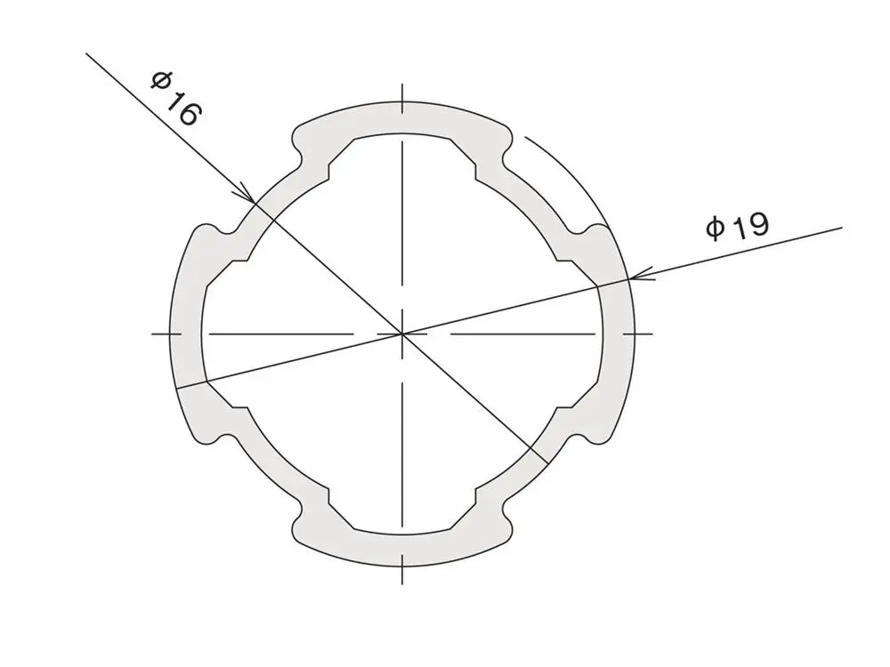
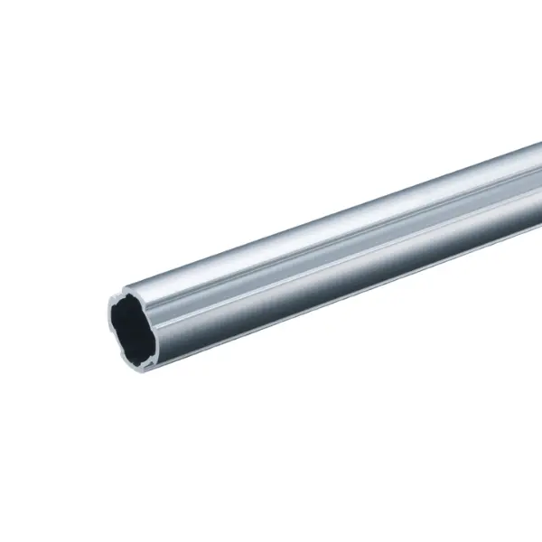
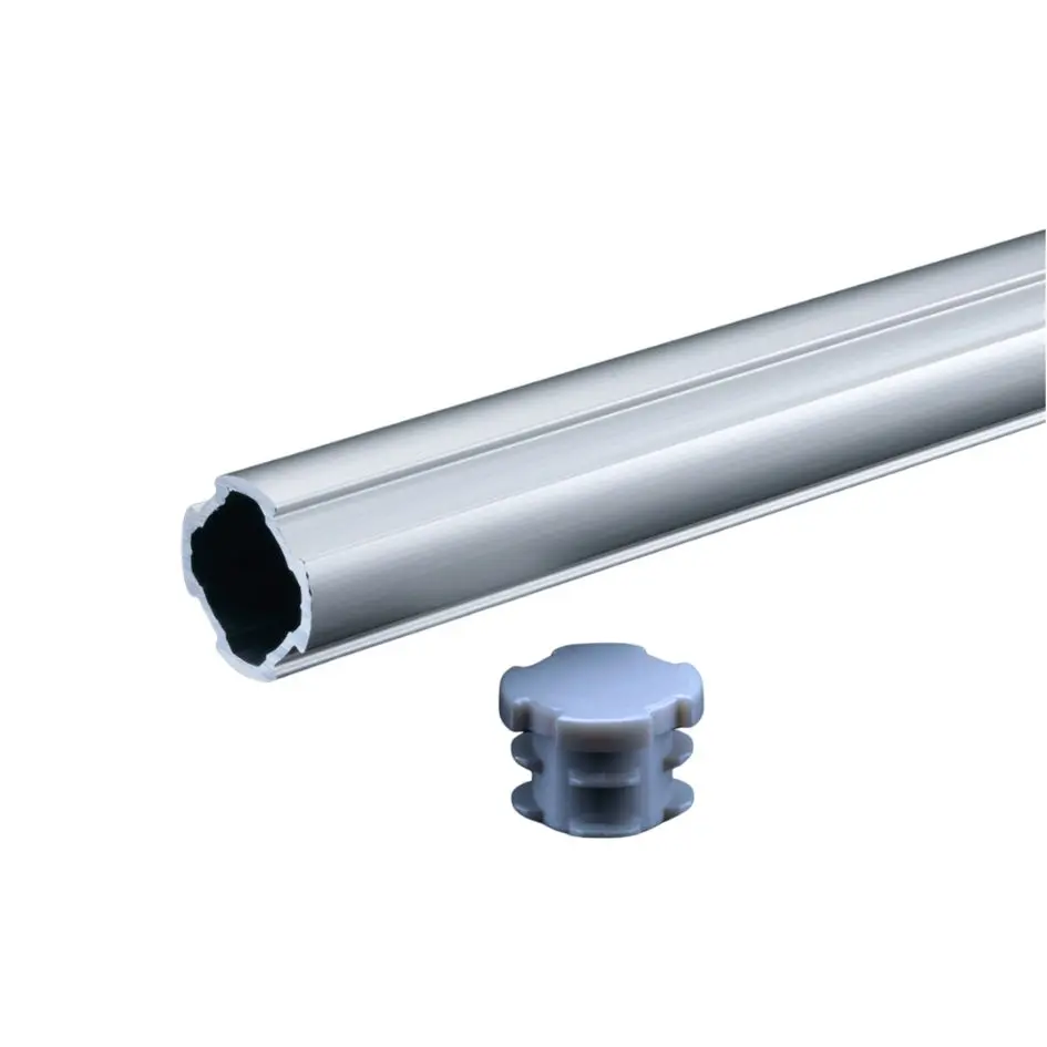
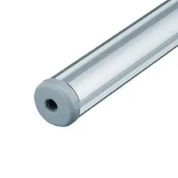
Anodised Ø 19 mm aluminium pipe from the Green Frame GF-S series: light (0.20 kg/m) for frames, dividers, guards and small structures, combinable with GF-N. 4000 mm bar or cut to length.
Green Frame · GF-S Ø 19 profiles
GF-S profile: Ø 19 mm aluminium pipe for light structures
The Ø 19 mm Green Frame pipe: it weighs 0.20 kg/m, little more than half the GF-N, and is used where the structure needs to be light and slim. You use it for light frames, dividers, guard bars, small trolleys and mechanisms, even within a GF-N structure thanks to the mixed connectors.
Why choose it
Ultra-light
0.20 kg/m: structures you move by hand and mechanisms with little moving mass.
Small footprint
The 19 mm diameter leaves more room for parts, hands and tools.
Combines with GF-N
Mixed 90°, parallel and cross connectors join it to Ø 28 and Ø 43 pipes.
Complete range
Inner and outer connectors, 45°, rotating, sliding and braces, all for Ø 19.
Choose it if…
- The structure carries light loads and needs to be slim.
- You are building dividers, guard bars or small frames.
- You want to add light parts to a GF-N structure.
Choose another solution if…
- The structure has to carry shelves or workstation loads: GF-N profile →
- You need a stiffer Ø 19 pipe: GF-S Hard profile →
- You want a slot for accessories on the Ø 19 pipe: GF-S profile with C6 slot →
Not sure which one to choose? Use the Green Frame quick guide →
Application example
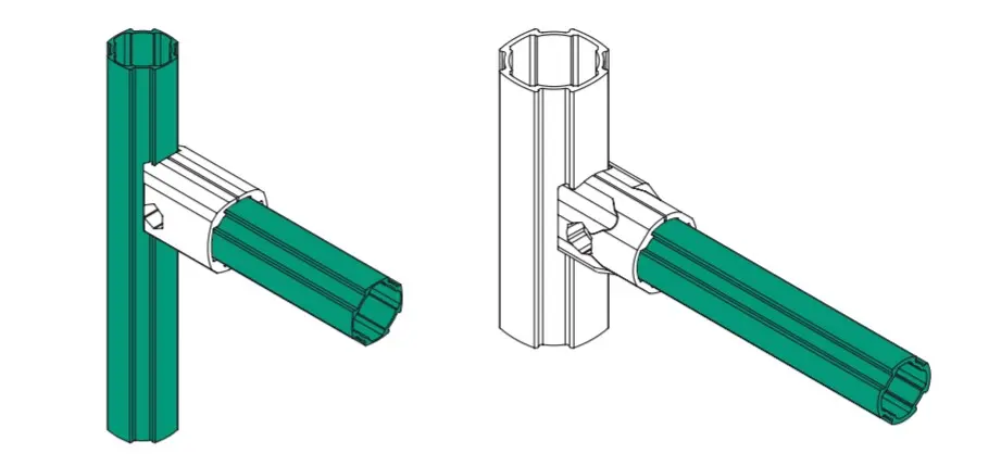
GF-S is used where GF-N would be oversized:
- Dividers and bars for guards and gates
- Small frames and supports on GF-N workstations
- Light mechanisms and moving parts
Most used connectors
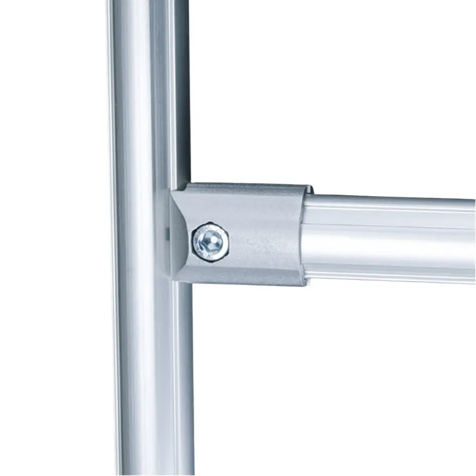
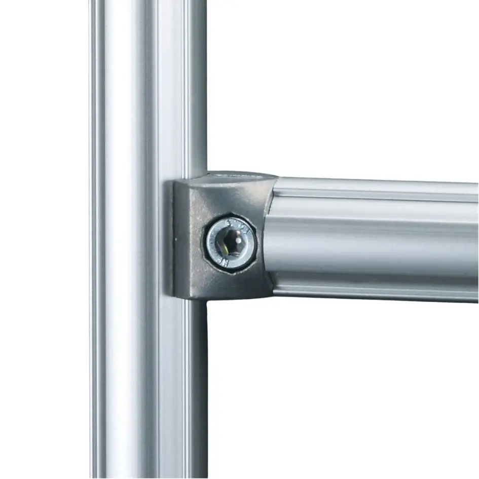
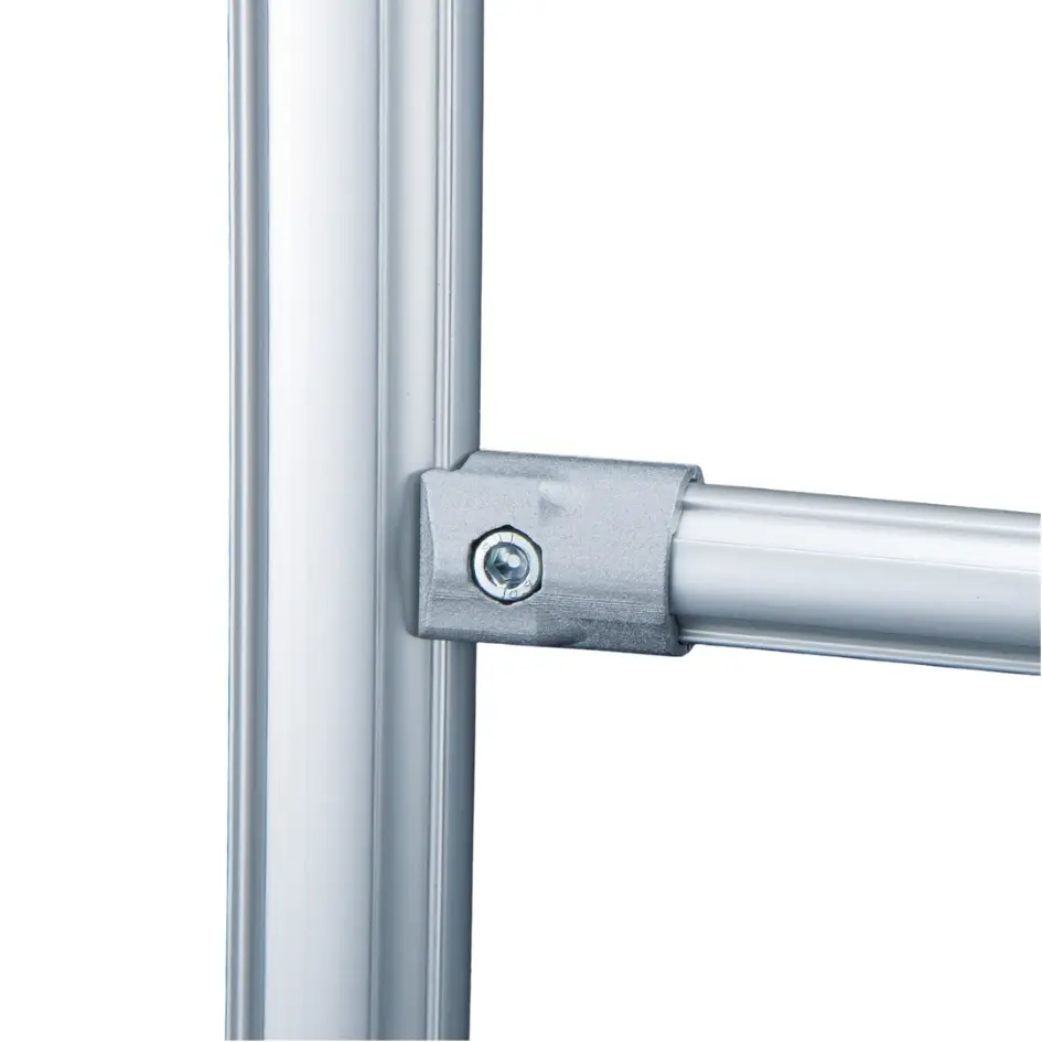
With the 45° brace you stiffen 90° joints between Ø 19 pipes.
How to combine it
GF-S works well together with the other series:
On GF-N and GF-G structures
With mixed connectors you attach a Ø 19 pipe to a Ø 28 or Ø 43 upright: at 90°, in parallel or crosswise.
Telescopic
The GF-S pipe slides inside the GF-N Hard profile: for adjustable uprights.
Feet
With the dedicated M6 threaded insert you fit feet on the Ø 19 pipe.
For short spans and light loads GF-S is enough; where the structure carries weight, use GF-N.
The LeanProducts service
From drawing to finished structure, with a single point of contact:
Design and load calculation
We start from your sketch or dimensions: we choose profiles and connectors and check spans, joints and loads.
Cut to length
We cut the profiles in our workshop to the lengths in the design, ready to assemble.
Kit or assembled structure
You receive the kit with the cut parts and the list of components, or the structure already assembled.
Spare parts and modifications
When the process changes we supply components and new cuts to modify or extend the structure.
Send us a sketch, a photo or the overall dimensions: we will reply with codes, quantities and cut lengths.
Technical data
| Specification | Value |
|---|---|
| Code | GFF-400 |
| Series | GF-S, Ø 19 mm pipe |
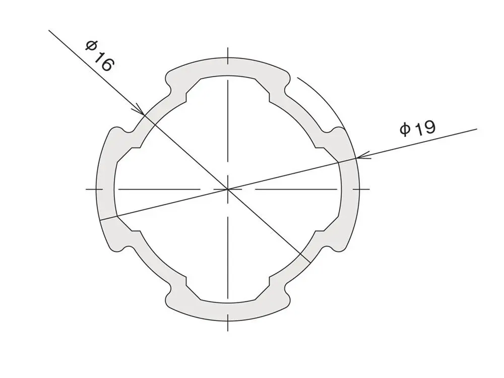
| Diameter | Ø 19 mm |
| Length | 4000 mm bar or cut to length |
| Weight | 0.20 kg/m |
| Material and finish | Anodised extruded aluminium |
| Moment of inertia | Ix = Iy = 0.27 × 10⁴ mm⁴ |
| Section modulus | Zx = Zy = 0.28 × 10³ mm³ |
| Suitable connectors | GF-S Ø 19 connectors; mixed GF-S with GF-N/GF-G |
| End caps | GF-S inner end cap GFA-403 |
| Feet | M6 threaded insert GFN-E07 |
The permissible load depends on span, profile orientation and joints: send us dimensions and weights and we will check the structure.
Related products
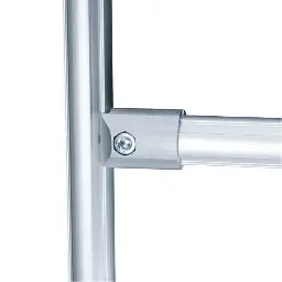 Outer 90° connector GF-SOuter 90° connector GF-S
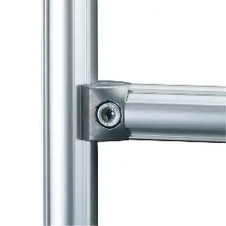 Inner 90° connector GF-SInner 90° connector GF-S
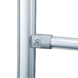 Outer 90° connector GF-S with GF-N/GMixed connector GF-S with GF-N/G
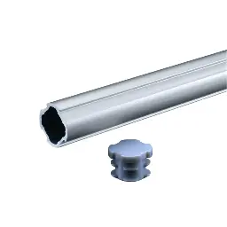 Inner end cap GF-SInner end cap GF-S
 45° brace GF-S45° brace GF-S
 M6 threaded insert for foot GF-SM6 threaded insert for feet
Not sure which profile to use?
Send us a sketch of the structure and the weight it has to support: we will tell you the profiles, connectors and cut lengths.