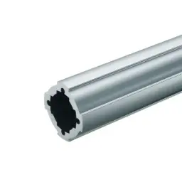
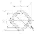
GF-G Hard profile
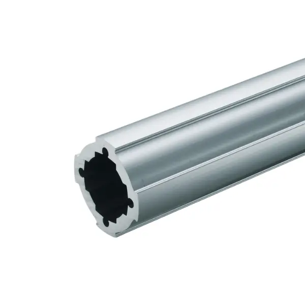
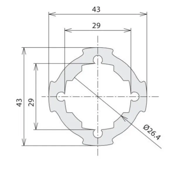
Thick-walled Green Frame Ø 43 mm pipe: about twice the bending resistance of GF-G, for joints subject to impacts. The GF-N Ø 28 slides inside. 1.57 kg/m, 4000 mm bar or cut to length.
Green Frame · GF-G Ø 43 profiles
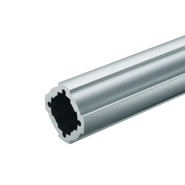
GF-G Hard profile: thick-walled Ø 43 mm pipe for joints under impact
The thick-walled GF-G Ø 43 mm pipe: about twice the bending resistance of the standard GF-G, designed for joints that take continuous impacts. A GF-N Ø 28 pipe slides inside it: with two pipes from the system you build sturdy telescopic uprights. It weighs 1.57 kg/m.
Why choose it
Withstands impacts
For joints that take continuous knocks: trolleys, end stops, pushed structures.
Double the resistance
About twice the bending resistance of GF-G, with the same diameter.
Telescopic uprights
The GF-N Ø 28 pipe slides inside: adjustable uprights with standard components.
Instead of GF-G
You use it only at the most stressed points; the rest of the structure stays in GF-G.
Choose it if…
- The joint takes continuous impacts.
- You need more strength while staying with the 43 diameter.
- You want telescopic uprights with a GF-N pipe inside.
Choose another solution if…
- The standard Ø 43 pipe is enough: GF-G profile →
- You need stiffness on the cross members, not on the joints: GF-G W profile →
- The structure is in Ø 28: GF-N Hard profile →
Not sure which one to choose? Use the Green Frame quick guide →
Application example
The GF-G Hard is used at the points of the structure that work hardest:
- Joints subject to impact on trolleys and handling structures
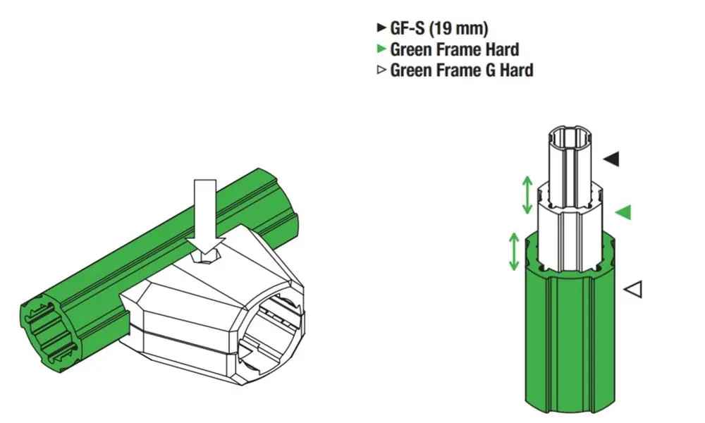
- Telescopic uprights with inner GF-N pipe
- Legs of heavy structures
How you use it
Where the Hard makes the difference:
In joints under impact
Use it as the pipe the connector clamps onto where the structure takes continuous knocks.
Telescopic
Slide a GF-N Ø 28 pipe inside the GF-G Hard and adjust the height.
Closed end
The end is closed with the dedicated inner end cap GFA-426.
We will advise you on how to lock the telescopic pipe according to the load.
The LeanProducts service
From drawing to finished structure, with a single point of contact:
Design and load calculation
We start from your sketch or dimensions: we choose profiles and connectors and check spans, joints and loads.
Cut to length
We cut the profiles in our workshop to the lengths in the design, ready to assemble.
Kit or assembled structure
You receive the kit with the cut parts and the list of components, or the structure already assembled.
Spare parts and modifications
When the process changes we supply components and new cuts to modify or extend the structure.
Send us a sketch, a photo or the overall dimensions: we will reply with codes, quantities and cut lengths.
Technical data
| Specification | Value |
|---|---|
| Code | GFF-209 |
| Series | GF-G, Ø 43 mm pipe |
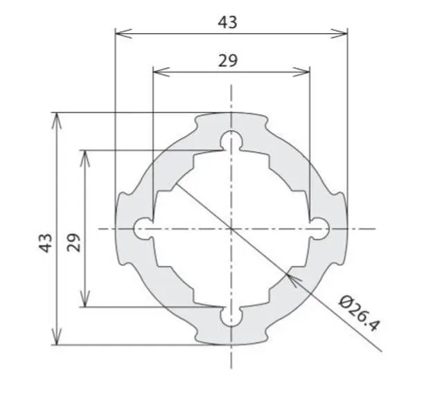
| Diameter | Ø 43 mm |
| Length | 4000 mm bar or cut to length |
| Weight | 1.57 kg/m |
| Material and finish | Anodised extruded aluminium |
| Moment of inertia | Ix = Iy = 9.18 × 10⁴ mm⁴ |
| Section modulus | Zx = Zy = 4.27 × 10³ mm³ |
| Bending resistance | About 2 times the GF-G profile |
| Inside | A GF-N Ø 28 pipe slides inside |
| Suitable connectors | GF-G Ø 43 connectors (models to be confirmed on the project) |
| End caps | Dedicated inner end cap GFA-426 |
The permissible load depends on span, profile orientation and joints: send us dimensions and weights and we will check the structure.
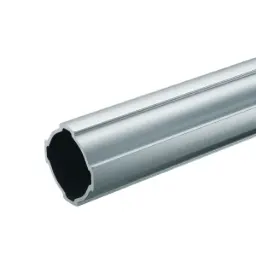 GF-G profileStandard GF-G profile
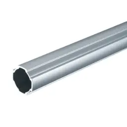 GF-N profileGF-N profile: slides inside
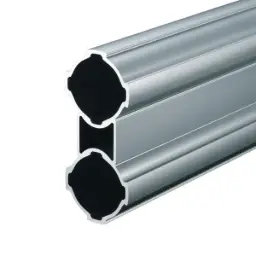 GF-G W profileGF-G W profile
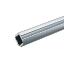 GF-N Hard profileGF-N Hard profile
Not sure which profile to use?
Send us a sketch of the structure and the weight it has to support: we will tell you the profiles, connectors and cut lengths.