- All Products
- AL Modular System
- Feet and wheels
- Accessories for feet
- Damping ring for levelling foot
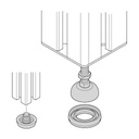
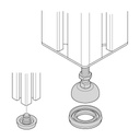
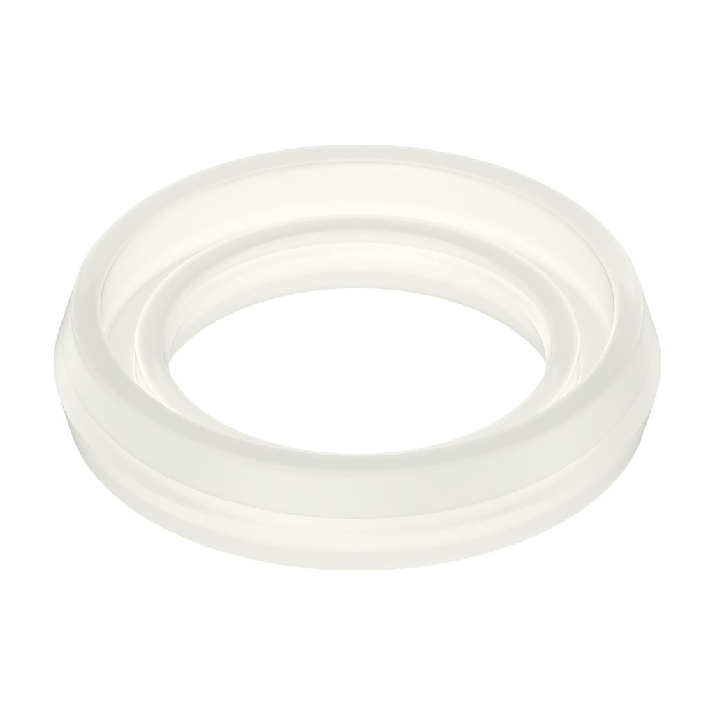
Damping ring for levelling foot
https://leanproducts.eu/shop/damping-ring-for-levelling-foot-2925 https://leanproducts.eu/web/image/product.template/2925/image_1920?unique=1d9bc53Polyurethane ring to fit under the base of the levelling foot: it damps vibration and electrically insulates the structure from the floor. For Ø 30, 44, 58 and 90 mm bases, load capacity 1600 to 3000 N.
AL Modular System · Feet and castors
Damping ring for levelling foot
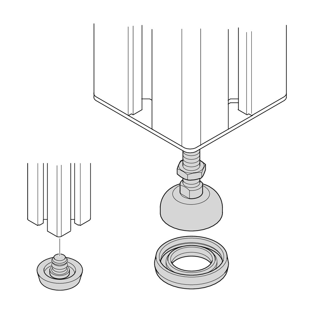
Under the base of the levelling foot, the damping ring stops machine or floor vibration from passing to the structure, and insulates it electrically. If you work in an ESD area, charges are dissipated in a controlled way with a set of grounding elements. It is made of natural PUR, hardness 70–80 Shore A, in the sizes of the Ø 30, 44, 58 and 90 mm bases.
Why choose it
Less vibration
Separates the structure from the floor: much less vibration gets through.
Electrical insulation
The structure does not touch the floor with metal parts; in ESD areas it is used with a grounding set.
Sized to the base
Four sizes, one for each base diameter of the levelling foot.
Data and compatibility
| Property | Value |
|---|---|
| For feet | Levelling foot with base Ø 30, 44, 58 or 90 mm |
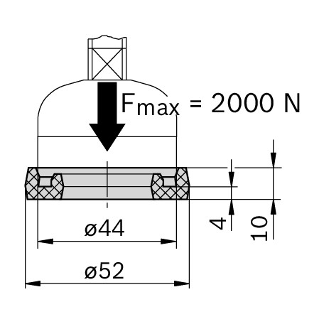
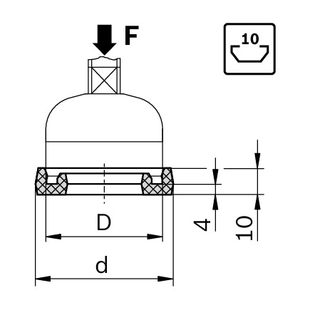
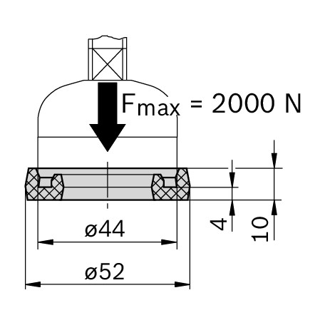
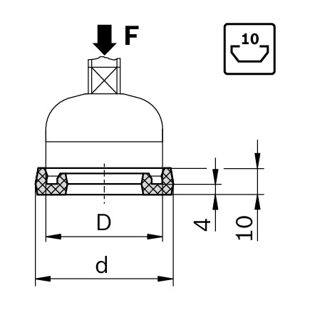
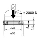
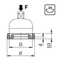
| Outer diameter d | 39 mm (Ø 30) · 52 mm (Ø 44) · 66 mm (Ø 58) · 98 mm (Ø 90) |
| Load capacity F | 1600 N (Ø 30) · 2000 N (Ø 44) · 2500 N (Ø 58) · 3000 N (Ø 90) |
| Material | Natural polyurethane (PUR), 70–80 Shore A |
| Versions | 4 codes |
Choose the variant above: data and code update in the Specifications tab.
Images and applications
Related products
Need help with your profile parts list?
Send us a sketch or the parts list: we will give you codes, accessories and cut lengths.
Specifications
| Colour | natural |
| Load capacity Fmax N | 2000 |
| Technical notes | Anello ammortizzatore per piede D44; d=52 mm; 70-80 Shore A |
| Diameter mm | 90 |
| Plate diameter | 44 |
| Slot mm | 10 |
| Material | PUR |
| Brand | Bosch Rexroth |
| Tags | |
|---|---|
| Tags |
Bosch 5S1
|
The same as the foot base diameter: Ø 30 ring for the Ø 30 base, Ø 44 for the Ø 44 base, and so on. The base diameter is in the name of the foot variant.
Yes: with the ring the limit becomes that of the ring, from 1600 N (Ø 30) to 3000 N (Ø 90), much less than the foot alone. If the structure is heavy, plan for more feet or a larger base.
If the workstation stands on a conductive floor, the feet would discharge to ground without control. With a damping ring or plate you insulate the feet and discharge passes only through the set, in a defined way.
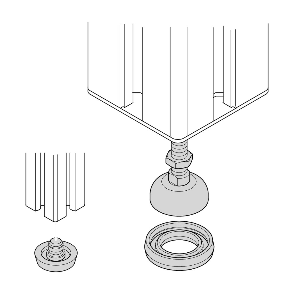
The damping ring is for levelling feet that are already mounted, the damping plate for modular feet made up of spindle and base plate.
Yes, but the ring insulates the structure from the floor: to dissipate charges in a controlled way you need a set of grounding elements. Ask us for the right one.
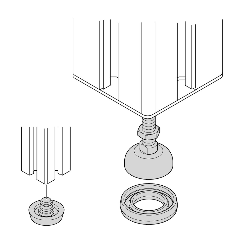
You can fit the polyurethane damping ring under the foot: it damps vibrations and is electrically insulating; in an ESD area discharge is handled with a grounding element set.
It is the width of the profile slot and determines which accessories you use. Slot C6 (6 mm) is for 20 series profiles, C8 (8 mm) for the 30 series, C10 (10 mm) for profiles from the 40 series upwards. Nuts, screws, brackets and cover caps are chosen by slot: each accessory's product page shows the right one.
Yes. You can order the full bar or the piece cut to the length you need: we do the cutting ourselves, in our workshop. Each profile's product page shows the maximum bar length and the minimum cut length.
Look at the moments of inertia Ix and Iy: the higher they are, the less the profile deflects under load. For the same section, “L” profiles are lightened and deflect a little more. For long spans or high loads move to a larger section or a tall profile (e.g. 45x90 instead of 45x45). If you send us drawing and loads, we will check the choice.
The T-nut is inserted from the front into the slot, even in an assembled structure, and positions itself when you tighten the screw: it is the standard choice for fixing accessories. The sliding block withstands higher forces, but normally has to be inserted from the profile end before closing the frame; spring versions stay where you put them.
The simplest way is the bracket, which joins two profiles at 90° with screws and nuts in the slot, without machining. For end, T, 45° or three-way connections there are dedicated connectors, some of which require profile machining as stated on their product page.
Yes, for several accessories (for example cover caps, hinges and nuts) there are conductive ESD versions, indicated in the name or variant. Tell us which EPA area you work in and we will confirm the components to use.
On each product page you will find the MGE catalogue pages to download as PDF, with dimensioned drawings and technical data; the Specifications tab shows the data for the variant you have chosen.
Yes. Send us the parts list or a sketch with dimensions: we give you codes, quantities and cut lengths and prepare the kit with profiles already cut and the accessories.