Product families / AL Modular System
AL Modular System: Bosch Rexroth aluminium strut profiles
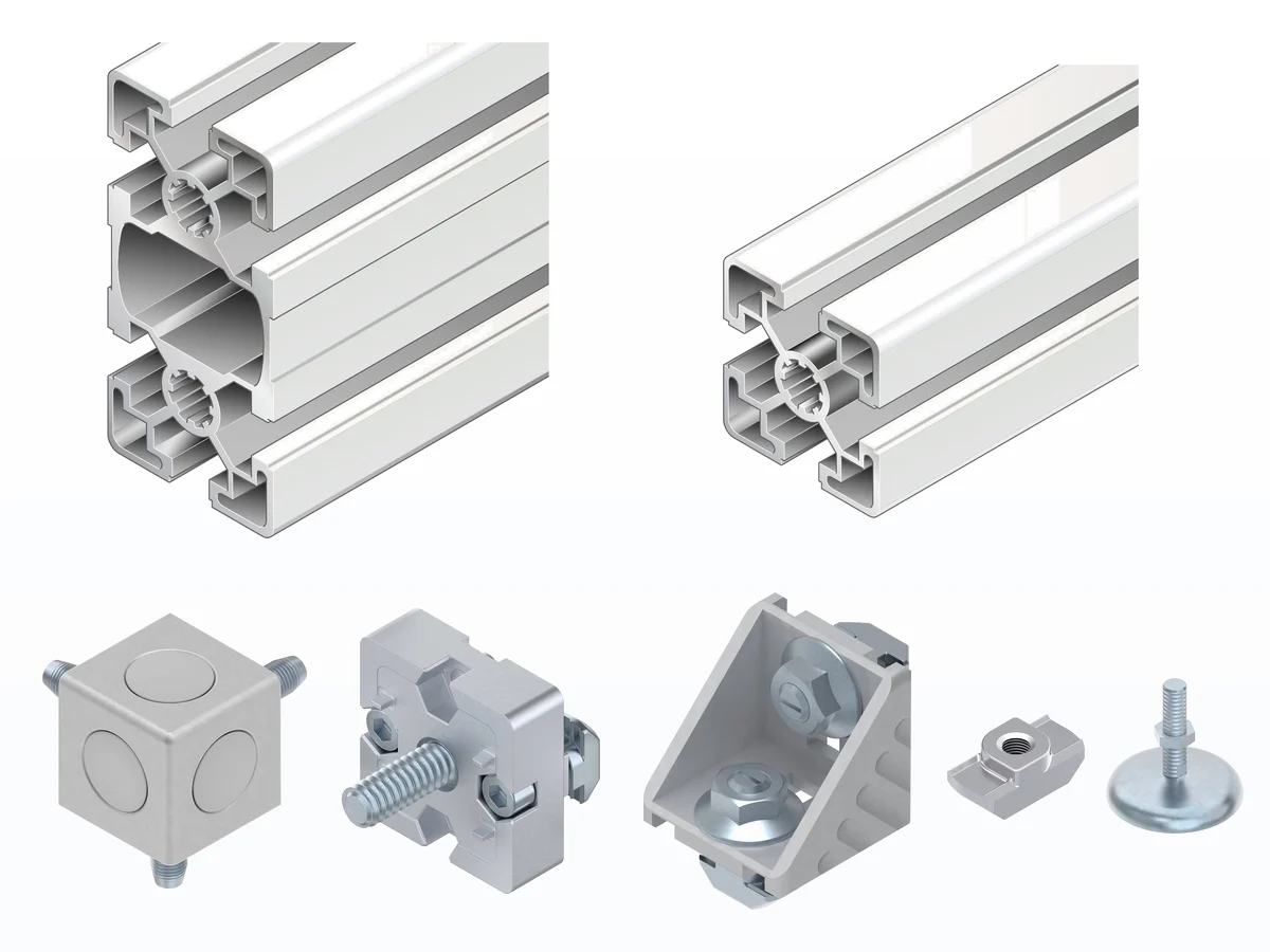
Slotted strut profiles with slot C6, C8 and C10 and all the elements of the MGE catalogue to build benches, workstations, machine guards and automation frames. Order the full bar or the profile cut to length, with brackets, T-nuts and cover caps for the same slot.
Why aluminium strut profiles
A strut profile structure is designed quickly, arrives cut and adapts when the line changes: it is the fastest way to build custom equipment on the shop floor.
Original Bosch Rexroth components
Profiles and accessories from the MGE catalogue with the manufacturer’s technical data: moments of inertia, weights and permissible loads for each element.
Full bar or cut to length
3000 or 6070 mm bars, or profiles cut in our workshop to the length you need, from 50 mm.
Easy to assemble and modify
Brackets, T-nuts and T-bolts are fixed in the slots without welding: when the process changes you move, extend or add an element.
Categories
Strut profiles
Connection elements
Cover caps and covers
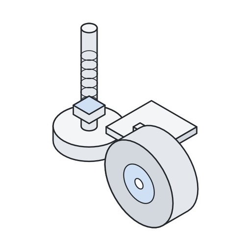
Feet and castors
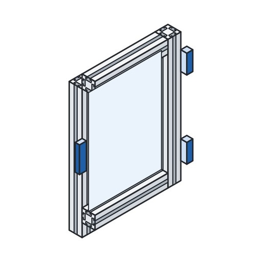
Doors and hinges
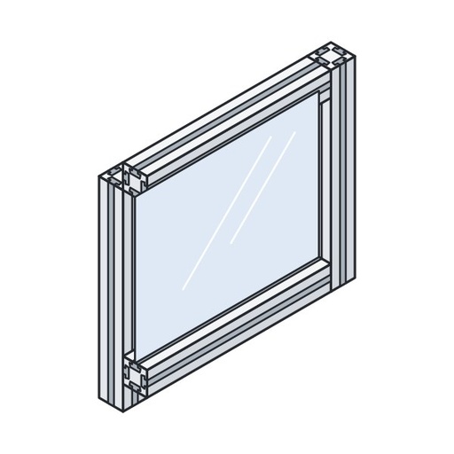
Panel element mounting
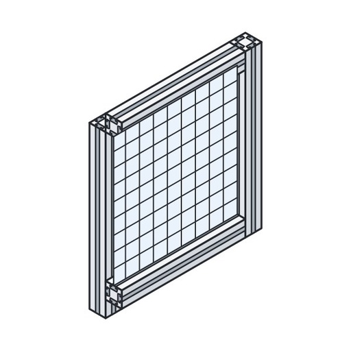
Guards and partition walls
Swivel joints
Compressed air elements
Manual material handling
Tools
ESD components
Other accessories
How to choose in 4 steps
1. Size and load
- Small, light structures: 20 and 30 series.
- Benches, guards and machine frames: 40, 45 and 50 series.
- Bases, gantries and long spans: 60, 80, 90 series and above.
2. Slot
- Slot C6 (6 mm) for 20 series profiles, C8 (8 mm) for the 30 series, C10 (10 mm) from the 40 series upwards.
- Nuts, screws, brackets and cover caps are chosen by slot.
- To join different series there are mixed accessories, for example C8/C10.
3. Stiffness
- Ix and Iy: the higher they are, the less the profile bends.
- Wx and Wy: indicate the bending strength.
- It and Wt: matter when the profile works in torsion.
4. Connections and finishes
- Brackets and connectors to join profiles, T-nuts to fix accessories.
- Cover caps and cover profiles to close ends and slots.
- Feet, castors, hinges and handles complete the structure.
The three slots: C6, C8 and C10
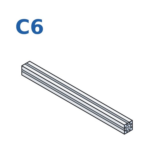 Slot C6 (6 mm)20 series profiles: compact, light structures.See the products →
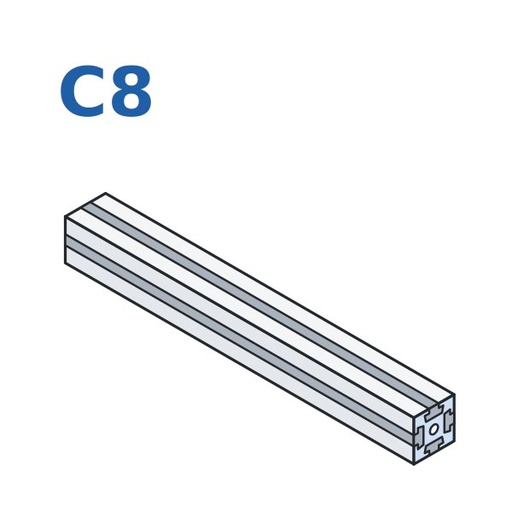 Slot C8 (8 mm)30 series profiles: light to medium frames, guards and display cases.See the products →
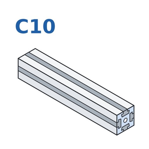 Slot C10 (10 mm)Profiles from the 40 series upwards: benches, guards and loaded structures.See the products →
Accessories are slot-specific: always check that the nut, screw or bracket is for the same slot as the profile.
Profile table by application
Main technical data of the aluminium strut profiles on the website. Click the name to open the profile’s product page.
Groups:Light applications (30)Medium applications (43)Heavy applications (26)Special profiles (9)
| Profile | Slot mm | Area cm² | Ix cm⁴ | Iy cm⁴ | Wx cm³ | Wy cm³ | It cm⁴ | Wt cm³ | Weight kg/m |
|---|---|---|---|---|---|---|---|---|---|
| Light applications · Small frames, guards, display cases, supports for sensors and devices: 20 (C6) and 30 (C8) series. | |||||||||
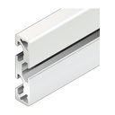 Profile 10x40 | C6 | 2.1 | 3.2 | 0.2 | 1.6 | 0.4 | – | – | 0.6 |
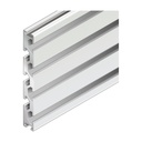 Profile 15x120 | C8 | 9.0 | 110.4 | 2.2 | 18.4 | 2.7 | – | – | 2.4 |
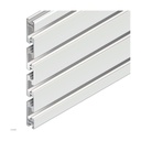 Profile 15x180 | C10 | 11.6 | 321.7 | 3.2 | 35.7 | 4.2 | – | – | 3.1 |
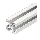 Profile 20x20 | C6 | 1.6 | 0.7 | 0.7 | 0.7 | 0.7 | 0.08 | 0.17 | 0.4 |
 Profile 20x20 R | C6 | 1.6 | 0.6 | 0.6 | 0.5 | 0.5 | 0.21 | 0.39 | 0.4 |
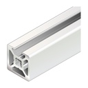 Profile 20x20 · 1N | C6 | 1.9 | 0.8 | 0.8 | 0.8 | 0.8 | – | – | 0.5 |
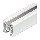 Profile 20x20 · 2N | C6 | 1.8 | 0.7 | 0.8 | 0.7 | 0.8 | 0.31 | 0.52 | 0.5 |
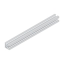 Profile 20x20 · 2NVS | C6 | 1.8 | 0.7 | 0.7 | 0.7 | 0.7 | 0.37 | 0.52 | 0.5 |
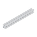 Profile 20x20 · 3N | C6 | 1.7 | 0.7 | 0.8 | 0.7 | 0.7 | 0.19 | 0.34 | 0.5 |
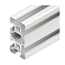 Profile 20x40 | C6 | 2.9 | 4.6 | 1.2 | 2.5 | 1.4 | 0.68 | 0.91 | 0.8 |
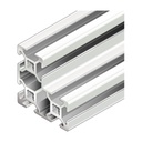 Profile 20x40x40 | C6 | 4.2 | 6.0 | 6.0 | 2.6 | 2.6 | 1.50 | 1.30 | 1.1 |
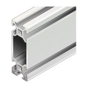 Profile 20x60 | C6 | 3.5 | 14.2 | 1.7 | 4.7 | 1.7 | 2.30 | 2.00 | 0.9 |
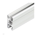 Profile 22.5x45 | C10 | 4.7 | 7.1 | 2.9 | 3.2 | 2.6 | – | – | 1.3 |
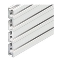 Profile 22.5x180 | C10 | 21.6 | 581.0 | 11.8 | 66.8 | 14.7 | – | – | 5.8 |
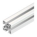 Profile 30x30 | C8 | 3.1 | 2.8 | 2.8 | 1.8 | 1.8 | 0.29 | 0.33 | 0.9 |
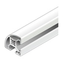 Profile 30x30 R | C8 | 2.9 | 2.3 | 2.3 | 1.4 | 1.4 | – | – | 0.8 |
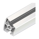 Profile 30x30 ° | C8 | 3.1 | 2.8 | 2.8 | 1.8 | 1.8 | 0.29 | 0.33 | 0.9 |
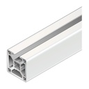 Profile 30x30 · 1N | C8 | 3.7 | 3.1 | 3.5 | 2.0 | 2.3 | 2.80 | 1.50 | 1.0 |
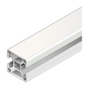 Profile 30x30 · 2N | C8 | 3.5 | 2.8 | 3.5 | 2.1 | 2.7 | 1.50 | 1.20 | 1.0 |
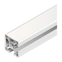 Profile 30x30 · 2NVS | C8 | 3.5 | 3.1 | 3.1 | 2.0 | 2.0 | 1.70 | 1.10 | 1.0 |
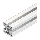 Profile 30x30 · 3N | C8 | 3.3 | 3.1 | 2.8 | 2.3 | 2.1 | 0.86 | 0.73 | 0.9 |
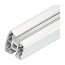 Profile 40x30 ° | C10 | 6.2 | 9.4 | 11.8 | 4.7 | 5.9 | – | – | 1.7 |
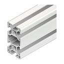 Profile 30x60 | C8 | 5.5 | 19.6 | 5.1 | 7.0 | 3.9 | 2.60 | 2.10 | 1.5 |
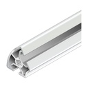 Profile 30x60 ° | C8 | 3.6 | 3.0 | 4.1 | 1.7 | 1.9 | – | – | 1.0 |
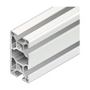 Profile 30x60 · 4N | C8 | 5.8 | 20.2 | 5.5 | 6.7 | 3.8 | 4.80 | 2.40 | 1.6 |
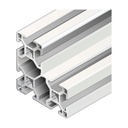 Profile 30x60x60 | C8 | 8.2 | 26.2 | 26.2 | 7.6 | 7.6 | 6.40 | 3.60 | 2.2 |
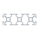 Profile 30x90 | C8 | 7.7 | 60.7 | 7.3 | 13.5 | 4.9 | – | – | 2.1 |
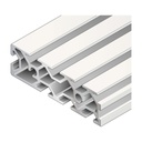 Grooved plate 30x100 L/R | C8 | 9.7 | 88.8 | 9.2 | 17.8 | 6.0 | – | – | 2.6 |
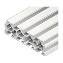 Grooved plate 30x100 M | C8 | 9.7 | 88.8 | 9.2 | 17.8 | 6.0 | – | – | 2.6 |
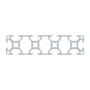 Profile 30x120 | C8 | 9.9 | 136.3 | 9.6 | 22.7 | 6.4 | – | – | 2.7 |
| Medium applications · Workbenches and workstations, machine guards, trolleys, plant frames: 40, 45 and 50 series (C10). | |||||||||
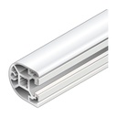 Profile 40x40 HR | C10 | 5.5 | 8.1 | 7.6 | 4.0 | 3.6 | – | – | 1.5 |
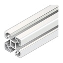 Profile 40x40L | C10 | 5.6 | 9.1 | 9.1 | 4.5 | 4.5 | 1.30 | 0.74 | 1.5 |
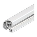 Profile 40x40L R | C10 | 5.0 | 7.2 | 7.2 | 3.6 | 3.6 | 2.50 | 2.00 | 1.3 |
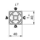 Profile 40x40L · 0N | C10 | 6.3 | 10.4 | 10.4 | 5.2 | 5.2 | – | – | 1.7 |
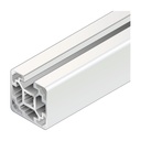 Profile 40x40L · 1N | C10 | 6.1 | 9.8 | 10.3 | 4.7 | 5.1 | 6.90 | 3.70 | 1.7 |
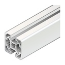 Profile 40x40L · 2N | C10 | 6.0 | 9.0 | 10.3 | 4.5 | 5.2 | 4.00 | 3.00 | 1.6 |
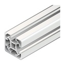 Profile 40x40L · 2NVS | C10 | 6.0 | 9.7 | 9.7 | 4.9 | 4.9 | 4.50 | 2.70 | 1.6 |
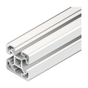 Profile 40x40L · 3N | C10 | 5.8 | 9.7 | 9.0 | 4.8 | 4.5 | – | – | 1.6 |
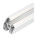 Profile 40x45 ° | C10 | 6.8 | 9.9 | 16.6 | 5.0 | 8.3 | – | – | 1.8 |
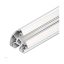 Profile 40x60 ° | C10 | 6.3 | 8.7 | 13.1 | 4.3 | 6.5 | – | – | 1.7 |
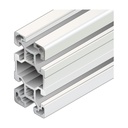 Profile 40x80L | C10 | 9.9 | 63.4 | 17.3 | 15.9 | 8.7 | 8.02 | 4.80 | 2.7 |
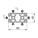 Profile 40x80L · 2N | C10 | 10.9 | 66.6 | 20.8 | 16.6 | 10.4 | – | – | 2.9 |
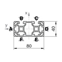 Profile 40x80L · 2NVS | C10 | 10.7 | 67.8 | 19.0 | 17.0 | 9.5 | – | – | 2.9 |
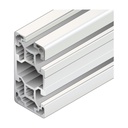 Profile 40x80L · 3NVS | C10 | 10.6 | 67.8 | 19.0 | 17.0 | 9.5 | – | – | 2.9 |
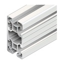 Profile 40x80L · 4N | C10 | 10.4 | 65.2 | 19.1 | 16.3 | 9.9 | – | – | 2.8 |
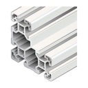 Profile 40x80x80L | C10 | 15.4 | 96.6 | 96.6 | 24.2 | 24.2 | – | – | 4.2 |
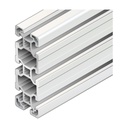 Profile 40x120L | C10 | 15.5 | 203.2 | 27.8 | 33.9 | 13.9 | 17.20 | 10.00 | 4.2 |
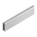 Profile 40x120L · 5N | C10 | 15.8 | 212.4 | 30.1 | 35.3 | 15.5 | – | – | 4.3 |
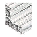 Profile 40x120x120L | C10 | 24.6 | 318.0 | 318.0 | 42.2 | 42.2 | – | – | 6.7 |
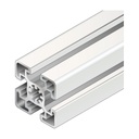 Profile 45x45 | C10 | 7.5 | 13.8 | 13.8 | 6.1 | 6.1 | 2.65 | 0.96 | 2.0 |
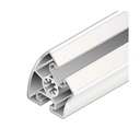 Profile 45x45 ° | C10 | 7.6 | 13.4 | 21.4 | 5.2 | 6.4 | – | – | 2.0 |
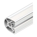 Profile 45x45HR | C10 | 6.6 | 11.0 | 10.7 | 4.8 | 4.4 | 7.60 | 3.40 | 1.8 |
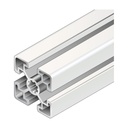 Profile 45x45L | C10 | 6.0 | 11.7 | 11.7 | 5.2 | 5.2 | 1.46 | 0.75 | 1.6 |
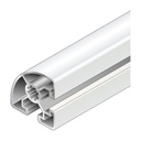 Profile 45x45L R | C10 | 4.9 | 8.6 | 8.6 | 5.0 | 5.0 | 3.30 | 2.80 | 1.3 |
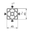 Profile 45x45L · 0N | C10 | 6.7 | 13.5 | 13.5 | 6.0 | 6.0 | – | – | 1.8 |
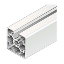 Profile 45x45L · 1N | C10 | 6.5 | 12.6 | 13.5 | 5.5 | 6.0 | 10.00 | 5.20 | 1.8 |
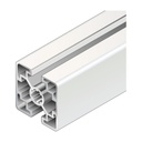 Profile 45x45L · 2N | C10 | 6.4 | 11.6 | 13.5 | 5.2 | 6.0 | 5.50 | 4.30 | 1.7 |
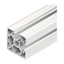 Profile 45x45L · 2NVS | C10 | 6.4 | 12.6 | 12.6 | 5.6 | 5.6 | 6.30 | 3.80 | 1.7 |
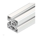 Profile 45x45L · 3N | C10 | 6.2 | 12.6 | 11.7 | 5.4 | 5.2 | – | – | 1.7 |
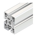 Profile 45x60 | C10 | 11.0 | 37.2 | 22.7 | 12.4 | 10.1 | 6.70 | 4.09 | 3.0 |
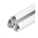 Profile 45x60 ° | C10 | 6.8 | 11.4 | 16.9 | 4.4 | 5.2 | 6.80 | 4.30 | 1.8 |
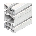 Profile 45x90 | C10 | 15.4 | 124.6 | 32.8 | 27.7 | 14.6 | 15.40 | 6.61 | 4.2 |
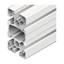 Profile 45x90L | C10 | 11.3 | 82.0 | 23.6 | 18.2 | 10.5 | 15.10 | 4.40 | 3.0 |
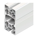 Profile 45x90L · 2N | C10 | 12.0 | 85.6 | 26.9 | 38.1 | 6.0 | – | – | 3.2 |
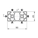 Profile 45x90L · 2NVS | C10 | 12.0 | 90.6 | 25.9 | 40.3 | 5.7 | – | – | 3.3 |
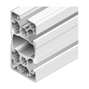 Profile 45x90L · 3NVS | C10 | 11.8 | 87.2 | 25.2 | 38.8 | 5.6 | – | – | 3.2 |
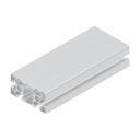 Profile 45x90L · 4N | C10 | 11.6 | 83.6 | 25.2 | 18.6 | 10.9 | – | – | 3.2 |
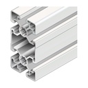 Profile 45x90SL | C10 | 9.0 | 73.4 | 18.1 | 16.3 | 8.0 | – | – | 2.4 |
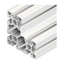 Profile 45x90x90L | C10 | 21.2 | 152.1 | 152.1 | 19.1 | 19.1 | – | – | 5.7 |
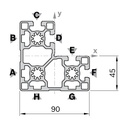 Profile 45x90x90L · 4N | C10 | 22.1 | 160.8 | 160.8 | 30.6 | 30.6 | – | – | 6.0 |
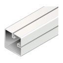 Profile 50x50 | C10 | 4.5 | 15.1 | 15.1 | 5.7 | 5.7 | – | – | 1.2 |
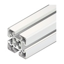 Profile 50x50L | C10 | 9.3 | 21.2 | 21.2 | 8.5 | 8.5 | 5.37 | 4.30 | 2.5 |
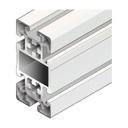 Profile 50x100L | C10 | 17.2 | 162.8 | 42.6 | 32.6 | 17.0 | 29.43 | 10.70 | 4.6 |
| Heavy applications · Bases, gantries, loaded structures and long spans: 60, 80, 90 and 100 series and tall profiles (C10). | |||||||||
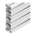 Profile 40x160L | C10 | 20.5 | 466.7 | 37.2 | 58.3 | 18.6 | 25.80 | 14.60 | 5.5 |
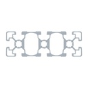 Profile 45x135L | C10 | 16.8 | 267.4 | 36.2 | 39.6 | 16.1 | – | – | 4.6 |
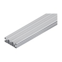 Profile 45x135L · 5N | C10 | 17.3 | 274.4 | 38.6 | 40.7 | 17.6 | – | – | 4.7 |
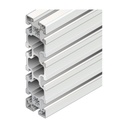 Profile 45x180 | C10 | 25.5 | 766.7 | 57.3 | 85.2 | 25.5 | 44.40 | 17.00 | 6.9 |
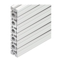 Profile 45x270 | C10 | 61.9 | 3962.0 | 118.0 | 300.2 | 61.6 | – | – | 16.7 |
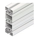 Profile 50x150L | C10 | 25.8 | 540.0 | 64.2 | 72.0 | 25.7 | – | – | 6.9 |
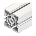 Profile 60x60 | C10 | 14.4 | 52.2 | 52.2 | 17.4 | 17.4 | 15.90 | 8.80 | 3.9 |
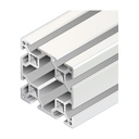 Profile 60x60 · 8N | C8 | 9.8 | 39.7 | 39.7 | 13.2 | 13.2 | – | – | 2.6 |
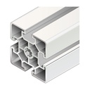 Profile 60x60L | C10 | 9.6 | 32.4 | 32.4 | 10.8 | 10.8 | 13.20 | 8.70 | 2.6 |
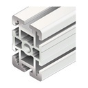 Profile 60x90 | C10 | 25.8 | 214.2 | 90.5 | 47.6 | 30.2 | – | – | 7.0 |
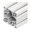 Profile 80x80L | C10 | 18.2 | 132.1 | 132.1 | 33.0 | 33.0 | 59.80 | 17.20 | 4.9 |
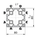 Profile 80x80L · 4N | C10 | 19.1 | 142.5 | 142.5 | 35.6 | 35.6 | – | – | 5.2 |
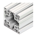 Profile 80x80L · 4NVS | C10 | 19.3 | 142.5 | 142.5 | 35.6 | 35.6 | – | – | 5.2 |
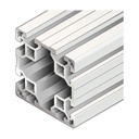 Profile 80x80L · 6N | C10 | 18.8 | 134.1 | 140.9 | 33.5 | 36.2 | – | – | 5.1 |
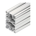 Profile 80x120L | C10 | 25.6 | 389.2 | 192.8 | 64.9 | 48.2 | 119.00 | 29.10 | 6.9 |
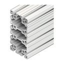 Profile 80x160L | C10 | 32.9 | 850.7 | 253.4 | 106.3 | 63.4 | 182.00 | 41.10 | 8.9 |
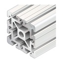 Profile 90x90 | C10 | 38.4 | 299.8 | 299.8 | 66.7 | 66.7 | 118.60 | 26.00 | 10.4 |
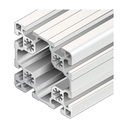 Profile 90x90L | C10 | 24.1 | 211.1 | 211.1 | 46.9 | 46.9 | 82.10 | 20.10 | 6.5 |
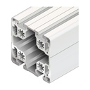 Profile 90x90L · 4N | C10 | 24.2 | 227.4 | 214.7 | 50.5 | 47.7 | – | – | 6.5 |
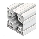 Profile 90x90L · 4NVS | C10 | 24.2 | 220.9 | 220.9 | 49.2 | 49.2 | – | – | 6.5 |
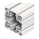 Profile 90x90SL | C10 | 14.1 | 130.2 | 130.2 | 28.9 | 28.9 | – | – | 3.8 |
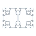 Profile 90x135L | C10 | 32.94 | 629.40 | 305.23 | 93.26 | 67.84 | – | – | 8.89 |
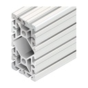 Profile 90x180 | C10 | 63.6 | 2138.3 | 544.3 | 237.6 | 121.0 | 429.00 | 64.00 | 17.2 |
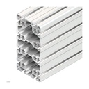 Profile 90x180L | C10 | 42.8 | 1380.0 | 401.0 | 153.3 | 89.1 | 257.00 | 47.10 | 11.6 |
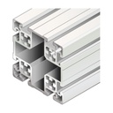 Profile 100x100L | C10 | 29.9 | 318.3 | 318.3 | 63.7 | 63.7 | 153.53 | 31.40 | 8.1 |
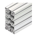 Profile 100x200L | C10 | 54.0 | 2133.1 | 602.1 | 213.3 | 120.4 | – | – | 14.6 |
| Special profiles · Reduced, angled or guiding sections for special requirements. | |||||||||
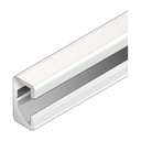 Profile 11x20 | C8 | 1.0 | 0.5 | 0.1 | 0.7 | 0.3 | – | – | 0.3 |
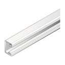 Profile 15x22.5 | C10 | 1.3 | 0.8 | 0.3 | 0.9 | 0.6 | – | – | 0.3 |
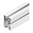 Profile 30x45 | C8/C10 | 4.0 | 8.1 | 3.9 | 3.9 | 2.9 | 1.30 | 1.30 | 1.1 |
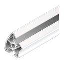 Profile 30x45 ° | C8 | 4.0 | 3.6 | 5.1 | 2.1 | 2.3 | – | – | 1.1 |
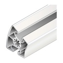 Profile 45x30 ° | C10 | 6.9 | 12.7 | 15.2 | 5.0 | 5.3 | 6.60 | 5.70 | 1.9 |
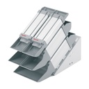 Material compartment profile ESD 90x45 | – | 7.0 | 20.7 | 54.3 | – | – | – | – | 1.8 |
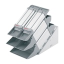 Material compartment profile 90x90 | C10 | 38.4 | 299.8 | 299.8 | 66.7 | 66.7 | 118.60 | 26.00 | 10.4 |
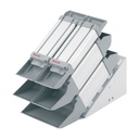 Material compartment profile ESD 90x90 | – | 9.6 | 118.8 | 88.1 | – | – | – | – | 2.5 |
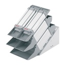 Material compartment profile ESD 180x90 | – | 15.5 | 208.2 | 597.5 | – | – | – | – | 4.2 |
Other profiles (data on the product page): Guide profile 30x45C, U-profile, U-profile ESD, Angle profile, Frame profile 22.5x45, ESD rubber profile for slot C10, Guide profile MV45, Clamping profile 1S C8, Clamping profile 2S C10, Clamping profile 2S C8, Suspension profile 15x30, Suspension profile 15x30 ESD, Handle profile SP 5, Handle profile SP 6, Edge protector SP 5, Edge protector SP 6, Sliding door profile Al 45, Sliding door profile Al Clip, bottom, Sliding door profile Al Clip, top, Material compartment profile 180x90, Material compartment profile 90x45, Cover profile, Guide profile 45x45, Double roller guide profile D28x55, Clamping profile C10 1S, Aluminium strut profile 22.5x30, Aluminium strut profile SP 2/B, Aluminium strut profile SP 2/B-100, Aluminium strut profile SP 2/B-50, Aluminium strut profile Ø28.
Ix, Iy: moments of inertia · Wx, Wy: section moduli · It, Wt: torsion factors. “L” profiles are lightweight versions. Alloy EN AW-6063, anodising E6/EV1. Indicative data: for loaded structures, check the deflection with the actual load, or send us the drawing.
Connection elements: how to choose
Eight ways to join two profiles at right angles, compared using the selection criteria from the Bosch Rexroth catalogue. Pick the criterion that matters most for your structure and look for the column with the most filled circles.
recommendedsuitablenot suitable
| Criterion | 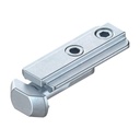 Tensioning connector | 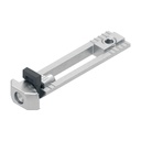 Slot connector | 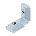 Inner bracket | 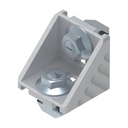 Bracket | 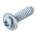 Central bolt | 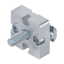 T-connector | 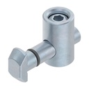 Quick connector | 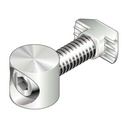 Bolt connector |
|---|---|---|---|---|---|---|---|---|
| High shear force | ||||||||
| High torque | ||||||||
| High torsional moment | ||||||||
| Minimal profile machining | ||||||||
| Quick assembly | ||||||||
| Low component cost | ||||||||
| Retrofitting in closed frames | ||||||||
| Adjustable position | ||||||||
| Support of panels and sheets | ||||||||
| Internal, concealed connection |
Profile machining as stated in the catalogue: central bolt M12 / Ø 9.8; quick connector and bolt connector Ø 17. The others fit the cut profile without drilling. The versions per slot (C6, C8, C10) or per section are on each element’s product page.
Other connection elements
| Joint | Elements | When to use them |
|---|---|---|
| Extending a profile in line | 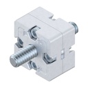 End connector 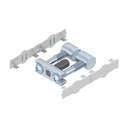 Longitudinal end connector 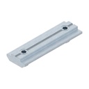 Profile connector 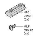 Connection kit | End-to-end connection of two profiles on the same axis. |
| Two profiles side by side | 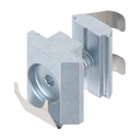 Parallel connector 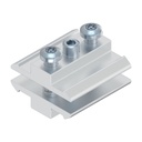 Parallel connector Quick | Parallel profiles joined along the slot, at any point. |
| Frame corner with three profiles | 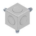 Cubic connector with screws and caps 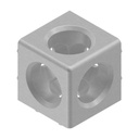 Cubic connector without screws 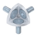 Corner bracket | 2- or 3-way node of the same section, torsion-resistant, no machining. |
| Diagonals, 45° and angles other than 90° | 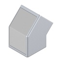 45° connector 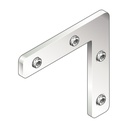 Mitre bracket 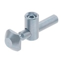 Bendable quick connector 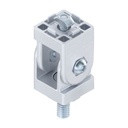 Joint for strut profiles | Diagonal braces to stiffen the frame, mitre-cut profiles, adjustable angles. |
| Reinforcements and steel angles | 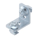 Steel angle 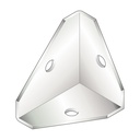 Sheet metal angle 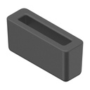 Intermediate element for bracket | Angles without centring lugs for loads and free angles; adapter to fit an bracket in the next larger slot. |
| Preventing rotation | 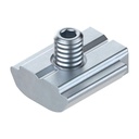 Anti-torsion element for central bolt | Increases the torsional strength of central bolt and quick connector joints, even after assembly. |
| Other quick connector versions | 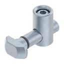 Quick connector 90° 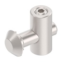 Quick connector with round head 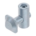 Quick connector slot 6 | Head turned by 90°, rotatable round head, version for the 20 series. |
| Floor fixing and shelf support | 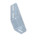 Foundation bracket 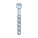 Foundation screw 10x100 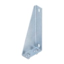 Sheet metal bracket 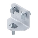 Support angle for round tube D28 | Anchoring structures to concrete, brackets for shelves and panel elements. |
Most popular products
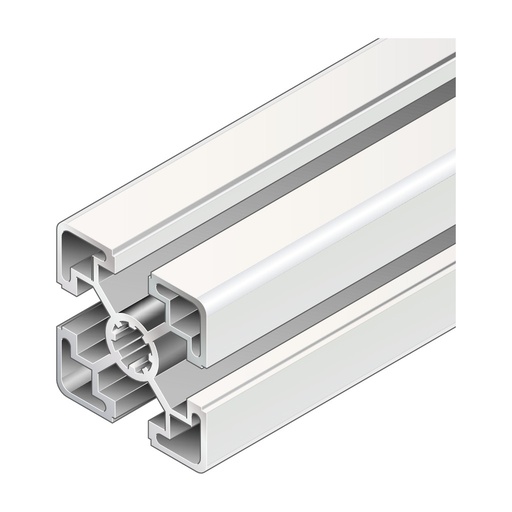
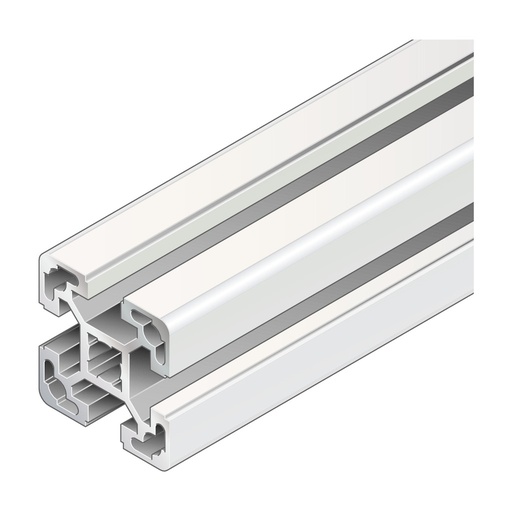
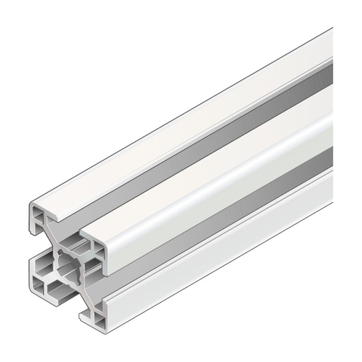
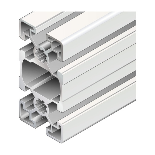
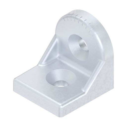
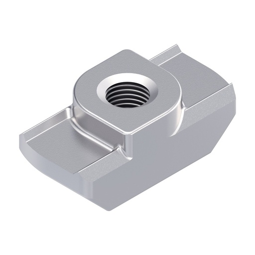
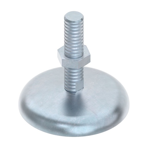
A profile plus brackets, T-nuts and cover caps for the same slot are enough for most frames; levelling feet bring them level.
The LeanProducts service
- Design and parts listWe start from your sketch or overall dimensions: we choose profiles and connection elements and prepare the parts list with codes and quantities.
- Cutting to lengthWe cut the profiles in our workshop to the project lengths, ready to assemble.
- Ready-to-assemble kitYou receive cut profiles, brackets, nuts and cover caps grouped for your structure.
- Spare parts and modificationsWhen you modify or extend the structure we supply profiles and components from the same system.
Send us a sketch, a photo or the parts list: we reply with codes, accessories and cut lengths.
FAQ
What is the difference between slot C6, C8 and C10?
It is the width of the profile slot and determines which accessories you use. Slot C6 (6 mm) is for 20 series profiles, C8 (8 mm) for the 30 series, C10 (10 mm) for profiles from the 40 series upwards. Nuts, screws, brackets and cover caps are chosen by slot: each accessory's product page shows the right one.
Can I have the profiles cut to length?
Yes. You can order the full bar or the piece cut to the length you need: we do the cutting ourselves, in our workshop. Each profile's product page shows the maximum bar length and the minimum cut length.
How do I choose the right profile for the load?
Look at the moments of inertia Ix and Iy: the higher they are, the less the profile deflects under load. For the same section, “L” profiles are lightened and deflect a little more. For long spans or high loads move to a larger section or a tall profile (e.g. 45x90 instead of 45x45). If you send us drawing and loads, we will check the choice.
T-nut or sliding block: which should I use?
The T-nut is inserted from the front into the slot, even in an assembled structure, and positions itself when you tighten the screw: it is the standard choice for fixing accessories. The sliding block withstands higher forces, but normally has to be inserted from the profile end before closing the frame; spring versions stay where you put them.
How are two profiles connected to each other?
The simplest way is the bracket, which joins two profiles at 90° with screws and nuts in the slot, without machining. For end, T, 45° or three-way connections there are dedicated connectors, some of which require profile machining as stated on their product page.
Are there ESD versions?
Yes, for several accessories (for example cover caps, hinges and nuts) there are conductive ESD versions, indicated in the name or variant. Tell us which EPA area you work in and we will confirm the components to use.
Where can I find drawings and full component data?
On each product page you will find the MGE catalogue pages to download as PDF, with dimensioned drawings and technical data; the Specifications tab shows the data for the variant you have chosen.
Can you prepare a kit with profiles and accessories?
Yes. Send us the parts list or a sketch with dimensions: we give you codes, quantities and cut lengths and prepare the kit with profiles already cut and the accessories.
Do you have a sketch or a parts list of the structure?
Send it to us: we reply with codes, quantities and cut lengths. The profiles arrive cut and ready to assemble.