Levelling foot
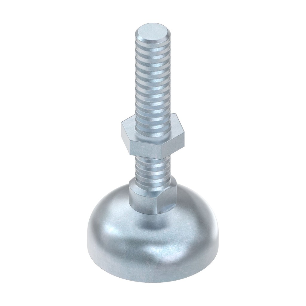
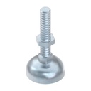
Levelling foot M8 with Ø 30 mm base for strut profile structures with slot C8 and C10: compensates floor unevenness up to 5°, carries 5000 N and screws into the tapped central hole of the profile. Conductive ESD version.
AL Modular System · Feet and castors
Levelling foot M8 - levelling feet for aluminium strut profiles
The levelling foot M8 is the foot you put under benches, frames and workstations to level them on the floor. It comes with spindle and base plate already assembled: tap the profile's central hole M8, screw in the foot and adjust the height. The articulated base compensates up to 5° of slope. It is the original Bosch Rexroth component, in zinc-plated steel and in ESD version.
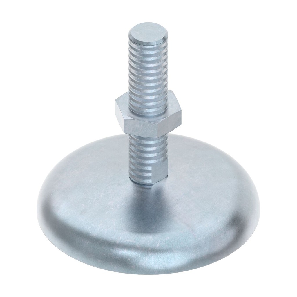
Why choose it
Levels the structure
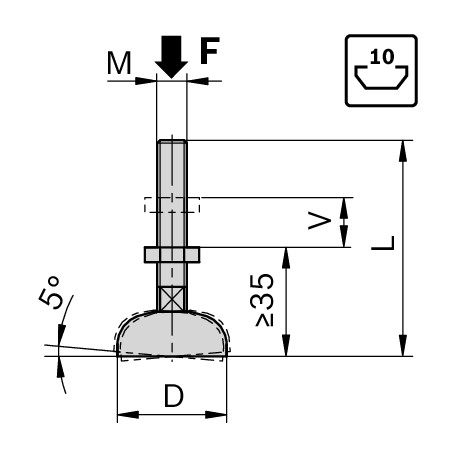
Adjust the height by screwing the foot, with an adjustment travel of 15 mm.
Follows the floor
The base plate tilts up to 5° and sits flat even on floors that are not perfectly level.
Pre-assembled
Spindle and base plate arrive assembled: screw it into the profile and you are done.
ESD version
Suitable for workstations and electrostatic protected areas.
Choose it if…
- You are levelling benches, workstations and light frames
- The profile has slot C8 or C10 and an M8-tappable central hole
- An adjustment travel of 15 mm is enough for you
- You work in an ESD area
Choose another solution if…
- The profile is series 20 with slot C6: on request
- The structure is heavy and you need more load capacity: on request
- You need to fix the structure to the floor: Base plate with floor fixing hole →
Not sure which profile to choose? Open the guide with the profile table →
The other feet in the range
Levelling foot M6
Ø 20 mm base for series 20 profiles.
Levelling foot M12
More load capacity for heavy benches and frames.
Levelling foot M16
For structures with high loads.
Choose the thread according to the profile's central hole and the weight to be carried.
The LeanProducts service
From parts list to ready-to-assemble kit, with a single point of contact:
Cutting to length
We cut the profiles in our workshop to the lengths in your parts list.
Check of codes and quantities
We start from the parts list or a sketch: we check nuts, connectors, feet and accessories for every slot and every joint.
Ready-to-assemble kits
You receive cut profiles and accessories grouped by structure, with the component list.
Spare parts
When you modify or extend the structure we supply the same original components.
Send us the parts list or a photo of the structure: we reply with codes and quantities.
Data and compatibility
| Property | Value |
|---|---|
| Slot | C8 e C10 |
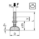
| Thread | M8, 65 mm long stem |
| Base plate | Ø 30 mm, tilts up to 5° |
| Adjustment travel | 15 mm |
| Load capacity | 5000 N |
| Material | Zinc-plated steel |
| ESD | Yes |
| Profile machining | M8 thread in the central hole |
| Code | 3 842 502 257 |
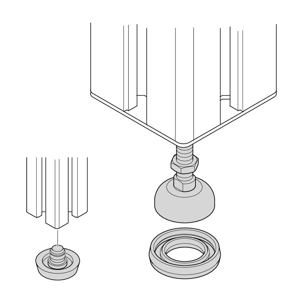
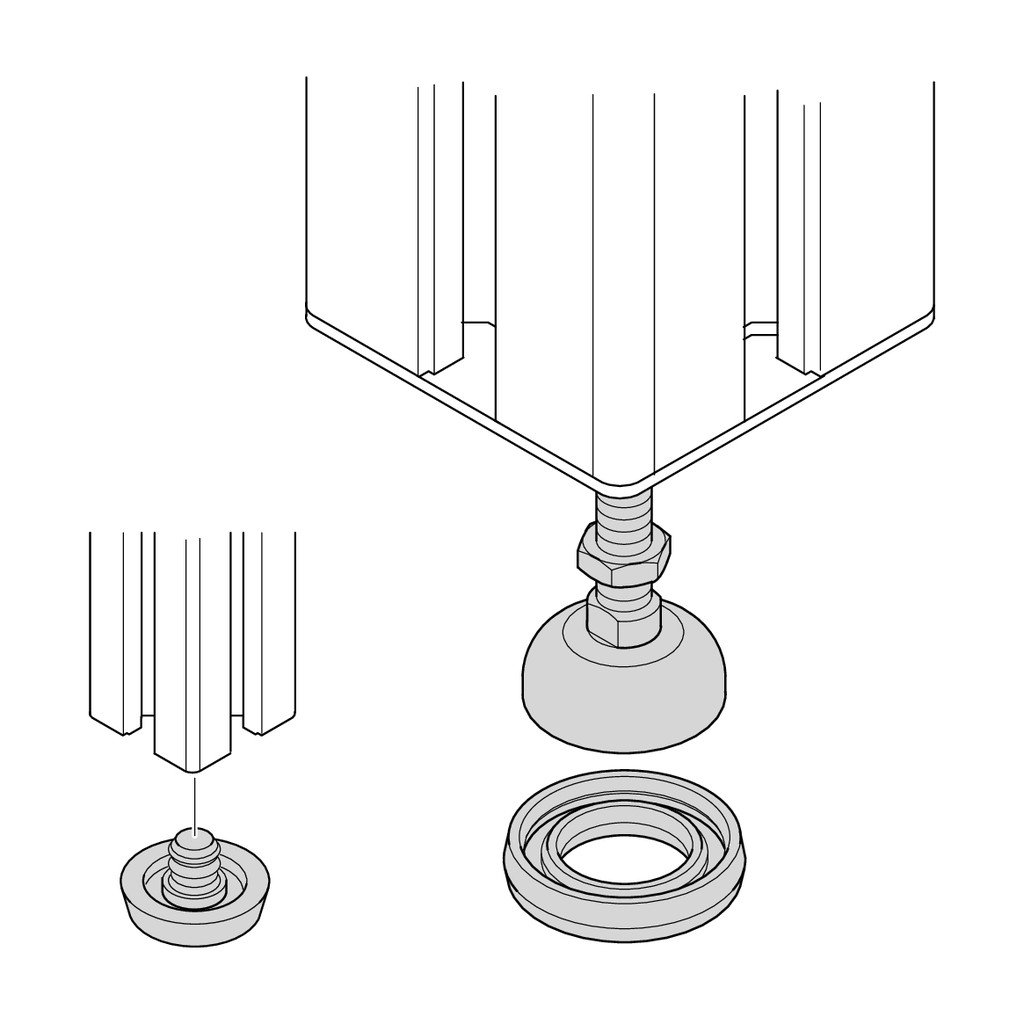
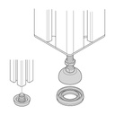
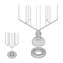
If you close the profile with an cover cap with hole, a support ring is needed under the foot: ask us for the code.
Downloads
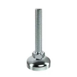 Levelling foot D30 H72 C10Levelling foot M12, Ø 30 base
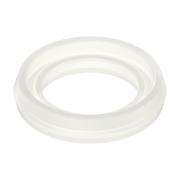 Damping ring for levelling footDamping ring
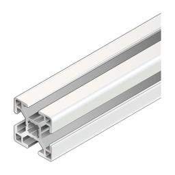 Aluminium strut profile 30x30Profile 30x30, slot C8
Need help with your profile parts list?
Send us a sketch or the parts list: we will give you codes, accessories and cut lengths.