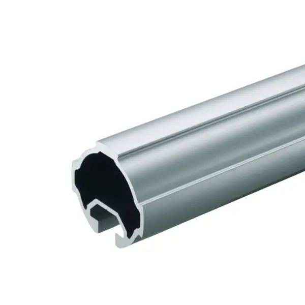


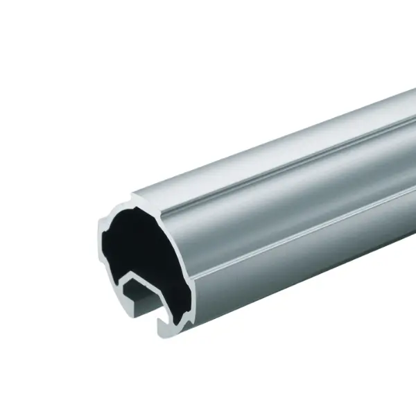
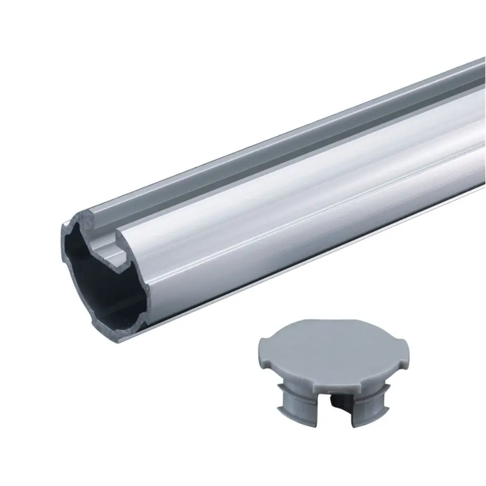
GF-G profile with C10 slot
Green Frame Ø 43 mm tube with C10 slot for T-nuts: you fix panels, brackets and accessories where needed and connect it to SF profiles. 0.98 kg/m, 4000 mm bar or cut to length.
Green Frame · GF-G Ø 43 profiles
GF-G profile with C10 slot: Ø 43 mm tube with slot for T-nuts and accessories
The GF-G Ø 43 mm tube with a 10 mm slot: with T-nuts you fix panels, brackets, hooks and screw-on accessories, and with the dedicated kit you connect it to SF square profiles. It is as stiff as the standard GF-G: over a 1000 mm span it takes up to 972 N at mid-span with 5 mm of deflection.
Why choose it
Screw fixings anywhere
With T-nuts in the slot you mount panels, brackets and accessories in any position you want.
As stiff as GF-G
Over 1000 mm it takes 875–972 N at mid-span, depending on how you orient the slot.
Bridge to SF profiles
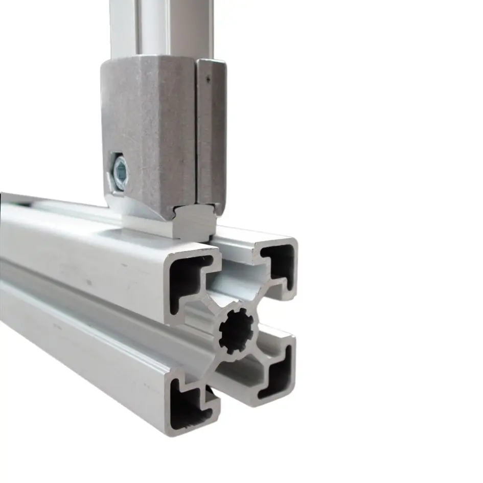
The dedicated kit connects the C10 slotted tube to SF square profiles.
In the Ø 43 series
End closed with the dedicated end cap and structure built with GF-G components.
Choose it if…
- On a Ø 43 structure you need to fix panels or screw-on accessories.
- You want to connect the tubular system to SF square profiles.
- You need a slot without giving up the stiffness of Ø 43.
Choose another solution if…
- You do not need the slot: the standard GF-G is lighter: GF-G profile →
- A C10 slot on a Ø 28 tube is enough: GF-N profile with C10 slot →
- You need more stiffness on the cross members: GF-G W profile →
Not sure which one to choose? Use the Green Frame quick guide →

Application example
The slotted GF-G is used for rigid structures that carry accessories:
- Panels and guards fixed with T-nuts
- Mixed structures with SF square profiles
- Equipped uprights with adjustable brackets and supports
What you complete it with
For the slot fixings we specify T-nuts and screws in the component list.
How you use it
Slot, T-nuts and SF profiles:
Orient the slot
With the slot on the side it takes 972 N at mid-span over 1000 mm, with the slot underneath 875 N.
T-nut
Insert the T-nut into the slot and fix the component with a screw: you move it whenever you like.
SF profiles
With the GF-SF kit you connect the tube to square-profile structures.
Tell us what you need to fix and where: we will propose profiles, fixings and quantities.
The LeanProducts service
From drawing to finished structure, with a single point of contact:
Design and load calculation
We start from your sketch or dimensions: we choose profiles and connectors and check spans, joints and loads.
Cut to length
We cut the profiles in our workshop to the lengths in the design, ready to assemble.
Kit or assembled structure
You receive the kit with the cut parts and the list of components, or the structure already assembled.
Spare parts and modifications
When the process changes we supply components and new cuts to modify or extend the structure.
Send us a sketch, a photo or the overall dimensions: we will reply with codes, quantities and cut lengths.
Technical data

| Specification | Value |
|---|---|
| Part number | GFF-205 |
| Series | GF-G, Ø 43 mm |
| Cross-section | 43 × 39 mm, 10 mm slot |
| Length | 4000 mm bar or cut to length |
| Weight | 0.98 kg/m |
| Material and finish | Anodised extruded aluminium |
| Moment of inertia | Ix = 5.21 × 10⁴ mm⁴ · Iy = 5.79 × 10⁴ mm⁴ |
| Section modulus | Zx = 2.43 × 10³ mm³ · Zy = 2.69 × 10³ mm³ |
| Load at centre, 1000 mm span | 875 N with the slot underneath, 972 N with the slot on the side (deflection 5/1000) |
| Suitable connectors | GF-G Ø 43 connectors (models to be confirmed on the project); kit GFA-609 for SF profiles |
| End caps | GF-G C10 inner end cap GFA-409 |
Loads concentrated at the centre of a tube fixed at both ends with connectors, span measured between the uprights: in a structure, joints and supports also count, and we carry out the full check on the design.
 GF-G C10 connector kit for SF profileConnector kit for SF profile
 Inner end cap GF-G with C10 slotGF-G C10 inner end cap
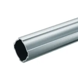 GF-G profileStandard GF-G profile
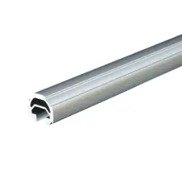 GF-N profile with C10 slotGF-N profile with C10 slot
Not sure which profile to use?
Send us a sketch of the structure and the weight it has to support: we will tell you the profiles, connectors and cut lengths.