- All Products
- AL Modular System
- Joints
- Swivel joint for support arm
Swivel joint for support arm
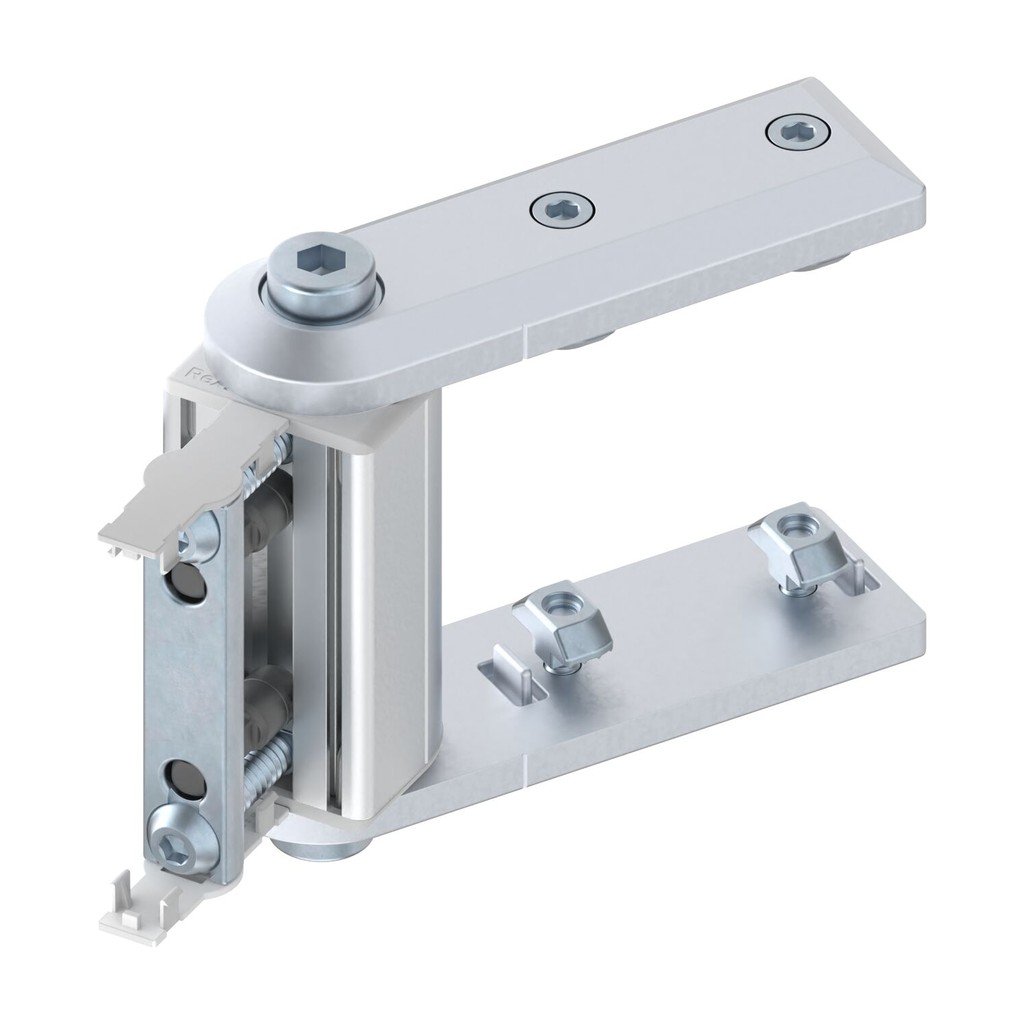
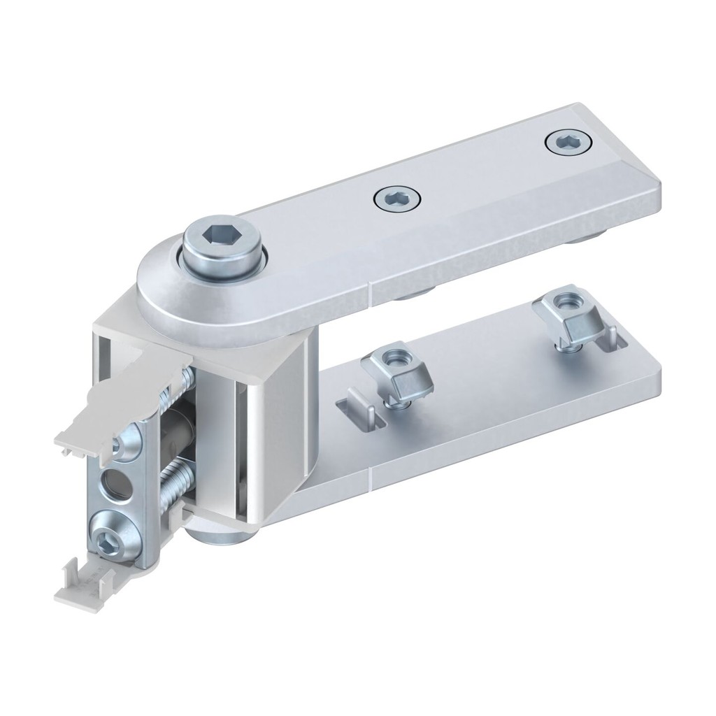
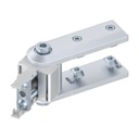
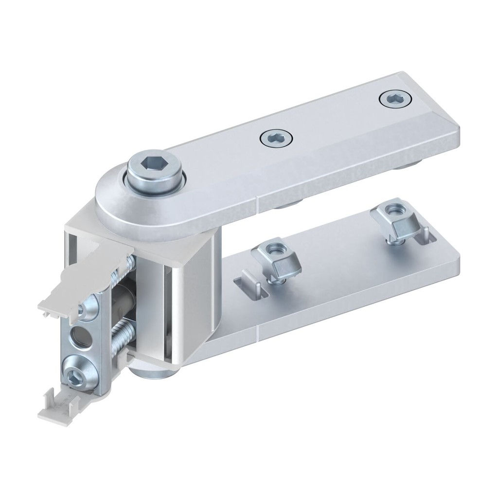
https://leanproducts.eu/shop/swivel-joint-for-support-arm-3580 https://leanproducts.eu/web/image/product.template/3580/image_1920?unique=1d9bc53Die-cast zinc swivel joint for connecting two profiles end-on in an adjustable way, for example for support arms, and locking them in any position. Sections 40x40, 40x80, 45x45 and 45x90, also designLINE silver; up to 150 Nm.
AL Modular System · Swivel joints
Swivel joint for support arm
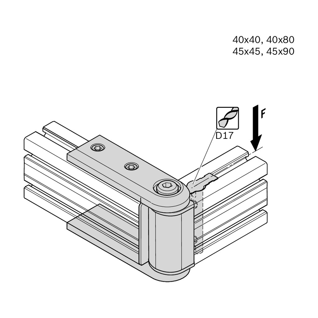
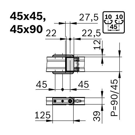
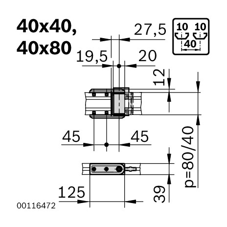
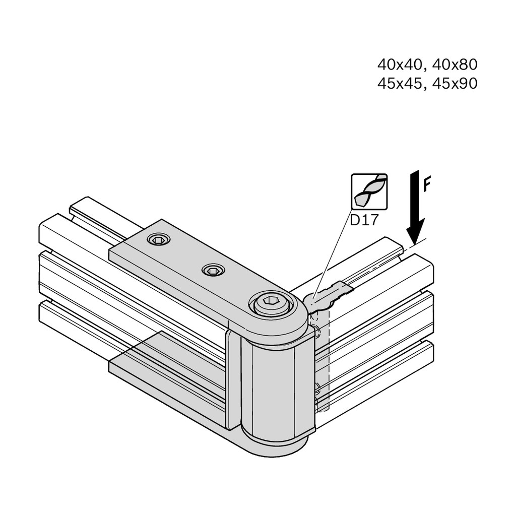
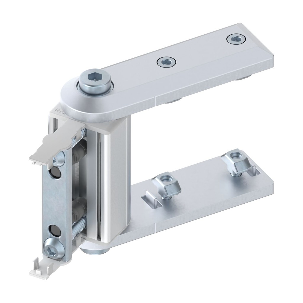
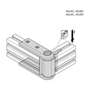
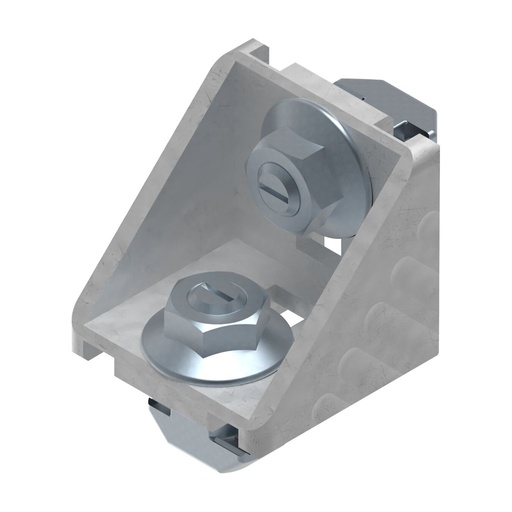
The swivel joint for support arm connects the end of one profile to another profile and lets it rotate: it is the solution for support arms and adjustable supports. You can lock it in any position. A Ø 17 through hole is needed on the profile; cover caps, bolt connectors and screws are included.
Why choose it
Adjustable and lockable
The arm rotates and locks in any position.
Clear moments
From 40 Nm on the 40x40 to 150 Nm on the 45x90.
Also designLINE
Silver lacquer RAL 9006 for visible workstations and machines.
Data and compatibility
| Property | Value |
|---|---|
| Slot | C10 |
| For profiles | 40x40 · 40x80 · 45x45 · 45x90 |
| Connection | End-on, adjustable, lockable in any position |
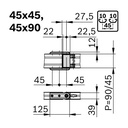
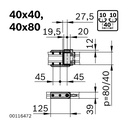
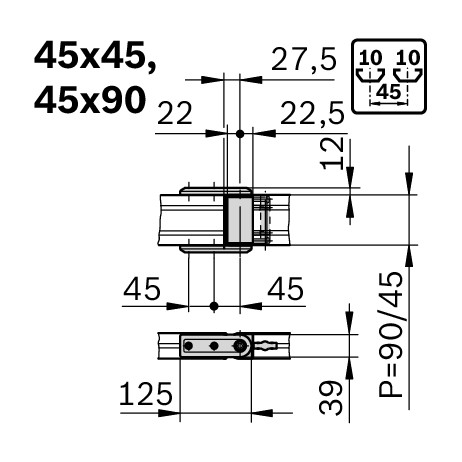
| Moment Mmax = F × L | 40x40: 40 Nm · 40x80: 130 Nm · 45x45: 50 Nm · 45x90: 150 Nm |
| Material | Die-cast zinc · designLINE silver-lacquered RAL 9006 · screws in galvanized steel |
| Profile machining | Through hole Ø 17 |
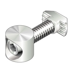
| Supply | Grey PP cover caps, bolt connectors, 4 ISO 4762 M6x16 screws |
| ESD | Conductive connection (the cover caps are not conductive) |
| Versions | 8 codes: 4 sections × standard or designLINE |
Choose the variant above: data and code update in the Specifications tab. Mmax is the permissible moment: force F times distance L from the swivel joint.
Images and applications
Downloads
Need help with your profile parts list?
Send us a sketch or the parts list: we will give you codes, accessories and cut lengths.
Specifications
| ESD | yes |
| Surface treatment | painted |
| Dimensions mm | 40x40 |
| Moment Mmax Nm | 50 |
| Production method | Die casting |
| Technical notes | Incl. grey PP cover caps (non-ESD), bolt connectors and 4x ISO 4762 M6x16; hole D17 |
| Diameter mm | 17 |
| Colour | RAL 9006 |
| Section | 40x40 |
| Slot mm | 10 |
| Material | Die-cast zinc |
| Finish | standard |
| Brand | Bosch Rexroth |
| Tags | |
|---|---|
| Tags |
Bosch 5S1
|
The swivel joint for support arm connects end-on: the end of the arm joins the profile and rotates. The swivel support joins two profiles at right angles. For the same section they allow the same moment, from 40 Nm on the 40x40 to 150 Nm on the 45x90.
The swivel support joins two profiles at right angles and lets them rotate one on the other. The swivel joint for support arm instead connects the end of the arm end-on to the profile. Permissible moments and sections are the same.
The limit is the moment: force times distance from the swivel joint. On the 45x45 it is 50 Nm, i.e. about 100 N (10 kg) at 500 mm; on the 45x90 150 Nm, about 300 N at the same distance. Send us the weight and length of the arm and we will choose the section with you.
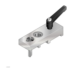
Yes, a Ø 17 through hole is needed for the bolt connectors included in the delivery. To make it in the right position there is the drilling jig for slot C10.
It is the width of the profile slot and determines which accessories you use. Slot C6 (6 mm) is for 20 series profiles, C8 (8 mm) for the 30 series, C10 (10 mm) for profiles from the 40 series upwards. Nuts, screws, brackets and cover caps are chosen by slot: each accessory's product page shows the right one.
Yes. You can order the full bar or the piece cut to the length you need: we do the cutting ourselves, in our workshop. Each profile's product page shows the maximum bar length and the minimum cut length.
Look at the moments of inertia Ix and Iy: the higher they are, the less the profile deflects under load. For the same section, “L” profiles are lightened and deflect a little more. For long spans or high loads move to a larger section or a tall profile (e.g. 45x90 instead of 45x45). If you send us drawing and loads, we will check the choice.
The T-nut is inserted from the front into the slot, even in an assembled structure, and positions itself when you tighten the screw: it is the standard choice for fixing accessories. The sliding block withstands higher forces, but normally has to be inserted from the profile end before closing the frame; spring versions stay where you put them.
The simplest way is the bracket, which joins two profiles at 90° with screws and nuts in the slot, without machining. For end, T, 45° or three-way connections there are dedicated connectors, some of which require profile machining as stated on their product page.
Yes, for several accessories (for example cover caps, hinges and nuts) there are conductive ESD versions, indicated in the name or variant. Tell us which EPA area you work in and we will confirm the components to use.
On each product page you will find the MGE catalogue pages to download as PDF, with dimensioned drawings and technical data; the Specifications tab shows the data for the variant you have chosen.
Yes. Send us the parts list or a sketch with dimensions: we give you codes, quantities and cut lengths and prepare the kit with profiles already cut and the accessories.