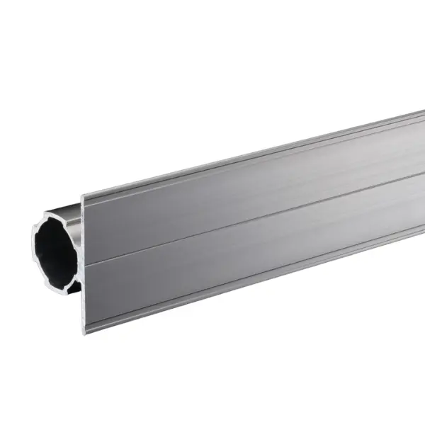


GF-N F50 profile
Green Frame Ø 28 mm tube with 50 mm flat flange: cross member and label holder in one piece, for small-parts holders, tags and signs. 0.65 kg/m, 4000 mm bar or cut to length.
Green Frame · GF-N Ø 28 profiles
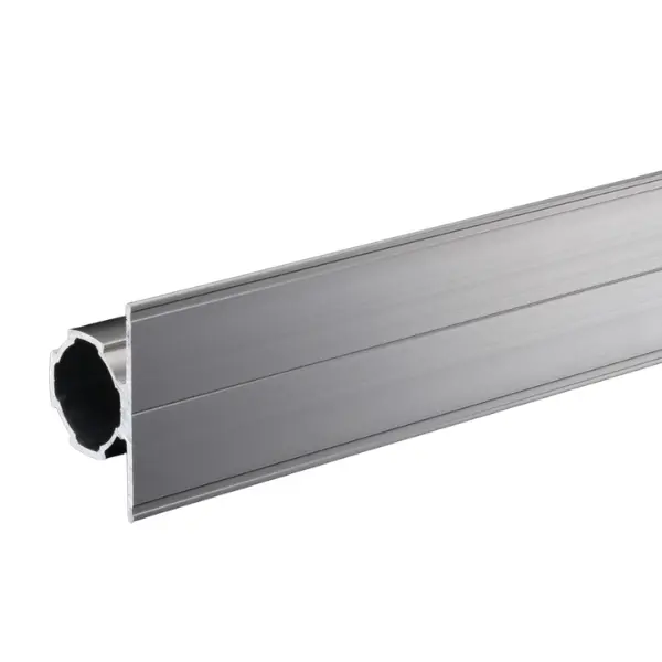
GF-N F50 profile: Ø 28 mm tube with 50 mm flat flange
A GF-N Ø 28 mm tube with a flat flange: on the flange you attach small-parts holders, tags and signs. It acts as both cross member and label holder in one piece, on workstations and lineside shelving. The flange stiffens the profile: its moment of inertia is almost three times that of the standard tube.
Why choose it
Label always in its place
On the flange you attach tags, signs and small-parts holders: every location has its name.
Cross member and support in one
A single profile acts as both structure and support for accessories: fewer parts, fewer joints.
28 series components
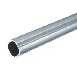
The tube is a GF-N Ø 28: you use connectors and end caps from the standard series.
Stiffer than the standard tube
The flange stiffens the profile: 3.04 × 10⁴ mm⁴ against 1.16 for GF-N.
Choose it if…
- You want to identify every picking location with tags or signs.
- You need to attach small-parts holders along a cross member.
- You need a wider flange than the F35's.
Choose another solution if…
- A narrower flange is enough, also to be used as a tray support: GF-N F35 profile →
- You want to fix accessories with screws anywhere: GF-N profile with C10 slot →
- You need a flange on a light Ø 19 tube: GF-S F35 profile →
Not sure which one to choose? Use the Green Frame quick guide →

Application example
The F50 is used on front cross members, where you need to see and pick:
- Assembly workstations: cross member with small-parts holders and tags
- Lineside shelving: a label for every location on the front profile
- Visual management: signs and indications directly on the structure
End caps
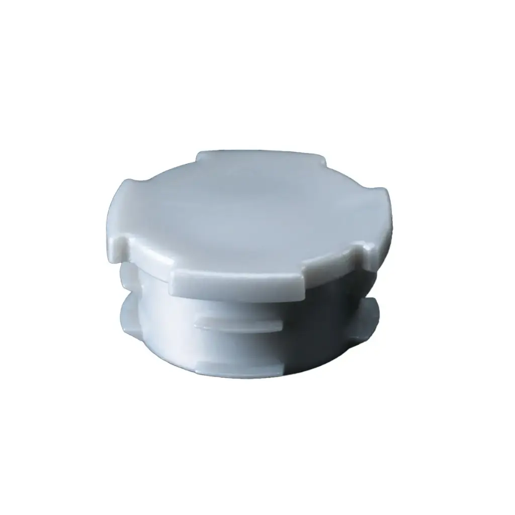
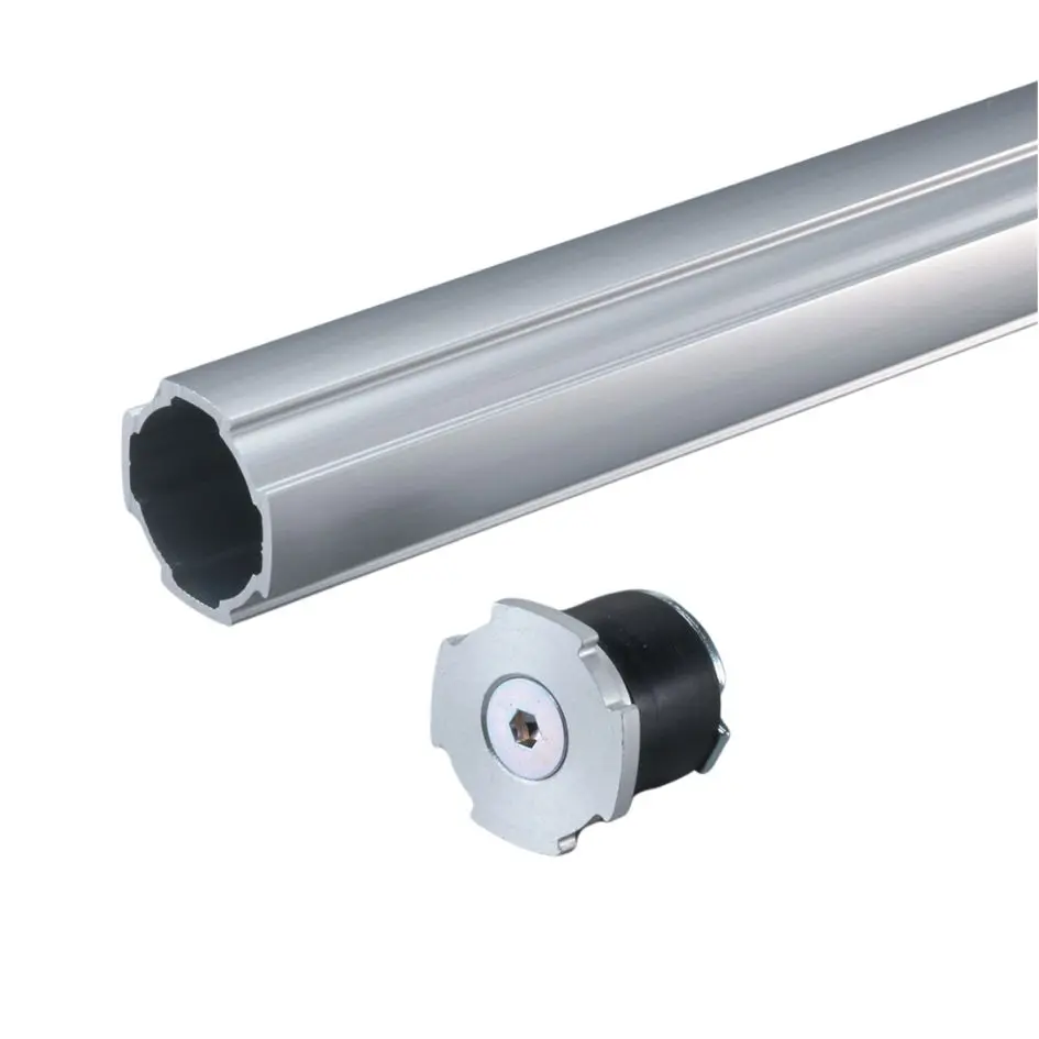
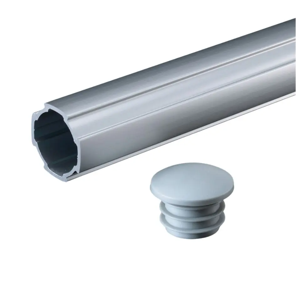
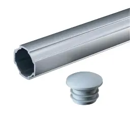
They are the same end caps as for the standard GF-N tube.
How you use it
Three typical uses of the flange:
Tags and signs
Apply labels or signs directly on the flange, along the whole cross member.
Small-parts holders
Fix small-parts containers on the flange: they stay within the operator's reach.
Adjustable
Like any GF-N tube, you move it up or down by loosening the connectors.
Tell us which way the flange should face: we take it into account when positioning the joints.
The LeanProducts service
From drawing to finished structure, with a single point of contact:
Design and load calculation
We start from your sketch or dimensions: we choose profiles and connectors and check spans, joints and loads.
Cut to length
We cut the profiles in our workshop to the lengths in the design, ready to assemble.
Kit or assembled structure
You receive the kit with the cut parts and the list of components, or the structure already assembled.
Spare parts and modifications
When the process changes we supply components and new cuts to modify or extend the structure.
Send us a sketch, a photo or the overall dimensions: we will reply with codes, quantities and cut lengths.
Technical data

| Specification | Value |
|---|---|
| Part number | GFF-005 |
| Series | GF-N, Ø 28 mm |
| Cross-section | Ø 28 mm tube with F50 flat flange, 1.9 mm thick |
| Length | 4000 mm bar or cut to length |
| Weight | 0.65 kg/m |
| Material and finish | Anodised extruded aluminium |
| Moment of inertia | Ix = 3.04 × 10⁴ mm⁴ · Iy = 2.56 × 10⁴ mm⁴ |
| Section modulus | Zx = 1.22 × 10³ mm³ · Zy = 1.24 × 10³ mm³ |
| Suitable connectors | GF-N Ø 28 connectors |
| End caps | Standard inner end cap GFA-400; alternatively aluminium GFA-E17, expanding GFA-C83, rounded GFA-404, ESD GFA-411 |
The permissible load depends on span, profile orientation and joints: send us dimensions and weights and we will check the structure.
 GF-N F35 profileGF-N F35 profile, narrower flange
 GF-N inner end capStandard inner end cap
 GF-N aluminium expanding end capExpanding end cap
 GF-N SR25 rounded inner end capRounded inner end cap
 Label holder GF-N/GLabel holder GF-N/G
 GF-N profileStandard GF-N profile
Not sure which profile to use?
Send us a sketch of the structure and the weight it has to support: we will tell you the profiles, connectors and cut lengths.